
Method for measuring flow rate and flow direction of single-well underground water and leaking point of reservoir, and measuring device thereof

A technology for groundwater and leakage points, which is applied in the direction of measuring devices, fluid velocity measurement, velocity/acceleration/shock measurement, etc., can solve the problems of high cost, impact on the environment, poor effect, etc., and achieve high precision and low measurement cost.

Active Publication Date: 2012-05-09
NANJING DIBA ENG TECH
View PDF8 Cites 30 Cited by
  • Summary
  • Abstract
  • Description
  • Claims
  • Application Information

AI Technical Summary

Problems solved by technology

[0004] The purpose of the present invention is to design a method that uses the excellent conduction characteristics of sonar signals in water bodies to realize direct or indirect sensitive measurement of seepage in view of the current problems of groundwater seepage detection, such as difficulty, high cost, poor effect and environmental impact. Therefore, it can be used to solve the problem of single well groundwater flow velocity and reservoir seepage, such as the measurement of the seepage inlet flow velocity of the bottom of the reservoir and underwater buildings, the hydrogeological measurement of single wells, the detection and prediction of leakage water on the pipe wall of underground railway tunnels, etc. Point measurement method and its measurement device

Method used


Image

  • Method for measuring flow rate and flow direction of single-well underground water and leaking point of reservoir, and measuring device thereof
  • Method for measuring flow rate and flow direction of single-well underground water and leaking point of reservoir, and measuring device thereof
  • Method for measuring flow rate and flow direction of single-well underground water and leaking point of reservoir, and measuring device thereof

Examples


Embodiment 1

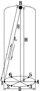
[0030] Such as figure 1 shown.

[0031] A method for sonar measurement of flow velocity and direction of groundwater in a single well, comprising the following steps:

[0032] First, install a ring of hydrophones at the lower end of a cylindrical measuring probe, install a hydrophone at the upper end of the cylindrical measuring probe, and install a magnetic heading sensor inside the cylindrical measuring probe;

[0033] Secondly, put the cylindrical measuring probe into the position to be tested, and calculate the seepage point according to the time difference between the lower hydrophone that first detected the acoustic signal and the upper hydrophone receiving the acoustic signal, and the distance between the upper and lower hydrophones The flow rate; record the intensity of the acoustic signal at the same time;

[0034] The calculation method of flow rate is:

[0035] Using the relationship between the difference of propagation velocity and the flow velocity of the meas...

Embodiment 2

[0047] Such as figure 1 shown.

[0048] A method for a groundwater seepage point of a reservoir, comprising the following steps:

[0049] First, install a ring of hydrophones at the lower end of a cylindrical measuring probe, install a hydrophone at the upper end of the cylindrical measuring probe, and install a magnetic heading sensor inside the cylindrical measuring probe;

[0050] Secondly, put the cylindrical measuring probe into the position to be tested, and calculate the seepage point according to the time difference between the lower hydrophone that first detected the acoustic signal and the upper hydrophone receiving the acoustic signal, and the distance between the upper and lower hydrophones The flow velocity, calculation method is identical with embodiment one; Record the intensity of acoustic wave signal simultaneously;

[0051] Third, the magnetic heading sensor is based on the calculation of the measurement intensity of the sensor that first senses the acousti...

Embodiment 3

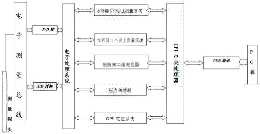
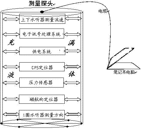
[0055] Such as figure 2 , 3 shown.

[0056] A single-well groundwater flow rate and direction sonar measuring instrument, which is mainly composed of a hydrophone, a magnetic heading sensor, a pressure sensor, a GPS locator, a signal processing circuit and a computer, such as figure 2 As shown, the hydrophone, magnetic heading sensor, pressure sensor, GPS positioning system and signal processing circuit are installed in a cylindrical detection head filled with liquid, such as image 3 As shown, the hydrophone is composed of a circle of hydrophones installed on the lower end of the cylindrical detection head and a hydrophone installed on the upper end of the cylindrical detection head; the hydrophone, the magnetic heading sensor, the pressure sensor and the GPS The signal output terminal of the locator is connected with the input terminal of the signal processing circuit at the same time, and the output terminal of the signal processing circuit is connected with the compute...


PUM

PropertyMeasurementUnit
Permeability coefficientaaaaaaaaaa

Abstract

A method for measuring the flow rate and the flow direction of single-well underground water and a leaking point of a reservoir, and a measuring device thereof are disclosed, wherein the measuring device is mainly composed of hydrophones, a magnetic heading sensor, a pressure sensor, a GPS (Global Positioning System) positioner, a signal processing circuit and a computer; the hydrophones, the magnetic heading sensor, the pressure sensor, the GPS positioning system and the signal processing circuit are mounted in a cylindrical detection head; the hydrophones include a circle of hydrophones mounted at the lower end of the cylindrical detection head and one hydrophone mounted at the upper end of the cylindrical detection head; the signal output ends of the hydrophones, the magnetic heading sensor, the pressure sensor and the GPS positioner are simultaneously connected to the input end of the signal processing circuit; and the output end of the signal processing circuit is connected to the computer. The method provided in the invention is simple, free of pollution and wide in application.

Description

technical field [0001] The invention relates to a civil engineering seepage measurement method and device, in particular to a groundwater three-dimensional flow velocity vector measurement method and device capable of measuring the velocity and direction of groundwater in a single well and measuring the seepage point of a reservoir. A single well groundwater flow velocity and direction measurement method and a reservoir seepage point measurement method and measurement device thereof are combined by using a hydrophone, a magnetic heading sensor, a pressure sensor and a GPS locator. Background technique [0002] Hydrogeological survey is the science of point observation and testing. The greater the density of measuring points, the higher the measurement accuracy. It is difficult to increase the point density by the traditional pumping water test method, and the obtained parameters cannot meet the needs of advanced hydrogeological evaluation calculation methods in terms of qua...

Claims


Application Information

Patent Timeline
IPC IPC(8): G01M3/02G01P5/24G01P13/02
Inventor 杜国平杜家佳宋晓峰
Owner NANJING DIBA ENG TECH
Learn More