
Anti-lock brake

A brake and anti-lock technology, applied in the direction of brakes, brake components, transportation and packaging, etc., can solve the problems of life and property safety threats, riding vehicle injuries, vehicle tail swinging, etc., to achieve reliable performance, safety protection, prevention of tail swing effect

Inactive Publication Date: 2012-05-09
张英楠
View PDF6 Cites 0 Cited by
  • Summary
  • Abstract
  • Description
  • Claims
  • Application Information

AI Technical Summary

Problems solved by technology

[0002] When a vehicle encounters a sudden situation while driving, it generally chooses emergency braking to force its wheels to stop rotating. However, due to the effect of inertia, a certain braking distance is required for the vehicle to stop; in addition, the wheel lock will also cause the riders to stop. Injuries, especially front wheel brakes, and vehicle tail swings and rollovers are also common, posing a certain threat to people's life and property safety

Method used


Image

  • Anti-lock brake
  • Anti-lock brake

Examples


Embodiment Construction

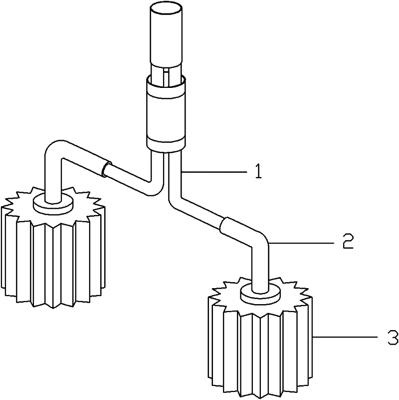
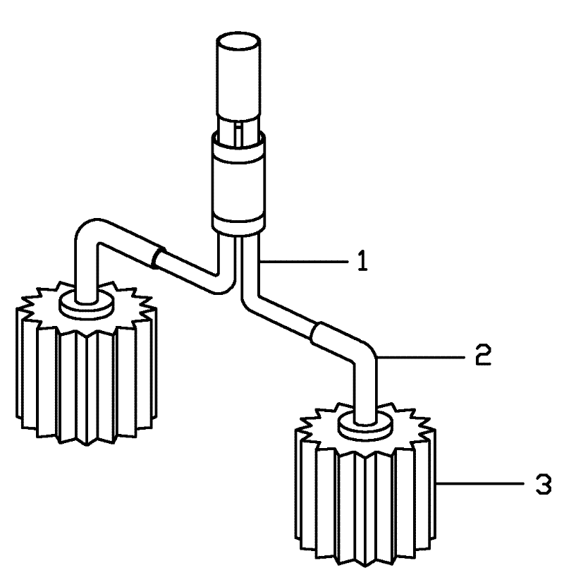
[0008] Such as figure 1 shown. An anti-lock brake, including a brake body, the brake body includes a brake line 1, a brake drum 2 and a brake pad 3, one end of the brake line 1 is connected to the brake pad 3 through the brake drum 2, and the other end is connected to the On the moving handle; the brake pad 3 is a star-shaped rotating structure, connected to the brake drum 2, the brake pad 3 is perpendicular to the axis of the wheel and distributed on both sides of the wheel rim.

[0009] When in use, hold the brake handle, and the brake pads 3 move upward toward the rim under the pulling force of the brake line 1. The two brake pads 3 move relative to each other at the same time, and the brake pads 3 apply extrusion and clamping force to the rim at the same time. 3 will also rotate with the inertial effect of the wheel, thereby playing the role of anti-lock.


PUM


Abstract

An anti-lock brake belongs to a vehicle braking system and mainly solves the problem that a traditional brake is easy to be locked. The anti-lock brake comprises a brake body, wherein the brake body consists of brake cables, brake drums and brake pads, one end of each brake cable is connected with the corresponding brake pad by the corresponding brake drum while the other end of the brake cable is connected onto a brake handle, each brake pad is in a star-shaped rotary structure and is connected onto the corresponding brake drum, and the brake pads are perpendicular to the axis of a wheel and distributed on two sides of a rim of the wheel. The anti-lock brake is simple in structure, reliable in performance, safe in use and convenient in installation, riders and passengers are effectively protected during emergency brake, and side slippage and fishtailing of the vehicle are prevented.

Description

technical field [0001] The invention relates to a vehicle brake system, in particular to an anti-lock brake. Background technique [0002] When a vehicle encounters a sudden situation while driving, it generally chooses emergency braking to force its wheels to stop rotating. However, due to the effect of inertia, a certain braking distance is required to stop the vehicle; in addition, the wheel lock will also cause people riding the vehicle to stop. Injuries, especially front wheel brakes, and vehicle tail swings and rollovers are also common, posing a certain threat to people's lives and property. Contents of the invention [0003] The object of the present invention is to provide an anti-lock brake, which has the functions of anti-lock and good braking effect. [0004] The technical solution adopted by the present invention to solve the technical problem is: an anti-lock brake, including a brake body, the brake body includes a brake line, a brake drum and a brake pad, a...

Claims


Application Information

Patent Timeline
IPC IPC(8): B60T1/06
Inventor 张英楠
Owner 张英楠
Learn More