Adjusting device of microwave antenna

An adjustment device and microwave antenna technology, which is applied in the field of communication, can solve the problems of low adjustment accuracy, signal jumping, and signal string movement, etc., and achieve the effects of continuous microwave signal changes, easy operation, and high adjustment accuracy

Active Publication Date: 2012-05-02
HUAWEI TECH CO LTD
View PDF4 Cites 9 Cited by
  • Summary
  • Abstract
  • Description
  • Claims
  • Application Information

AI Technical Summary

Problems solved by technology

[0007] The purpose of the present invention is to provide a microwave antenna adjustment device, which is used to solve the problems of signal jumping caused by nonlinear adjustment, signal string vibration during fastening, and low adjustment accuracy in the prior art.

Method used


Image

  • Adjusting device of microwave antenna
  • Adjusting device of microwave antenna
  • Adjusting device of microwave antenna

Examples


Embodiment Construction

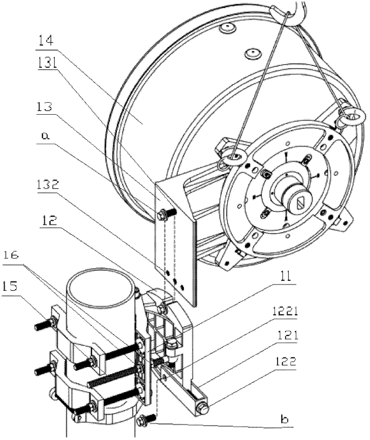
[0025] The core of the present invention is to provide an adjusting device for a microwave antenna. The adjusting device adjusts the position of the microwave antenna through a worm gear mechanism to realize linear transmission. During the adjustment process, the microwave signal is continuous without bounce, and the adjustment accuracy is high and the operation is simple.

[0026] In order to enable those skilled in the art to better understand the technical solutions of the present invention, the present invention will be further described in detail below with reference to the accompanying drawings and specific embodiments.

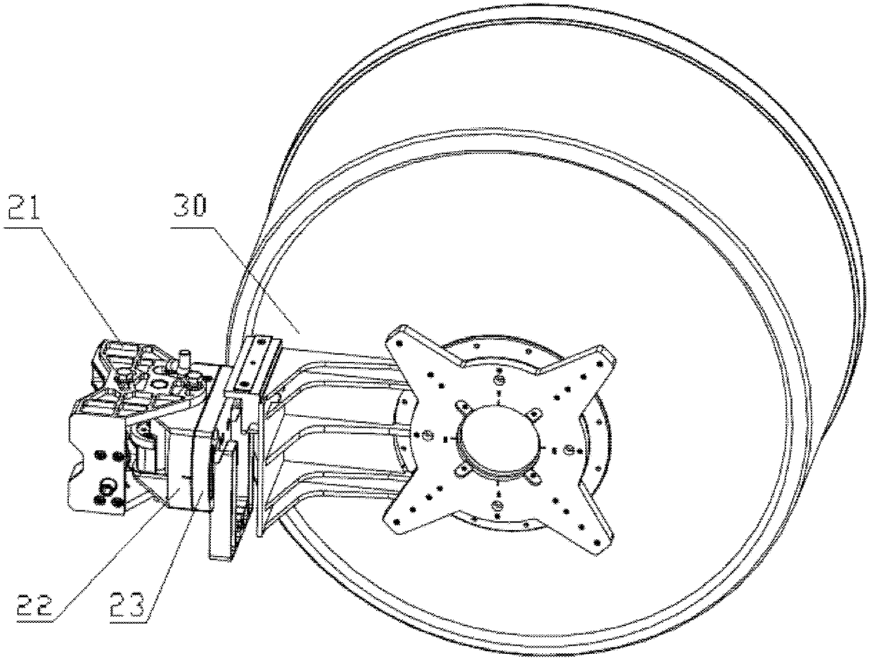
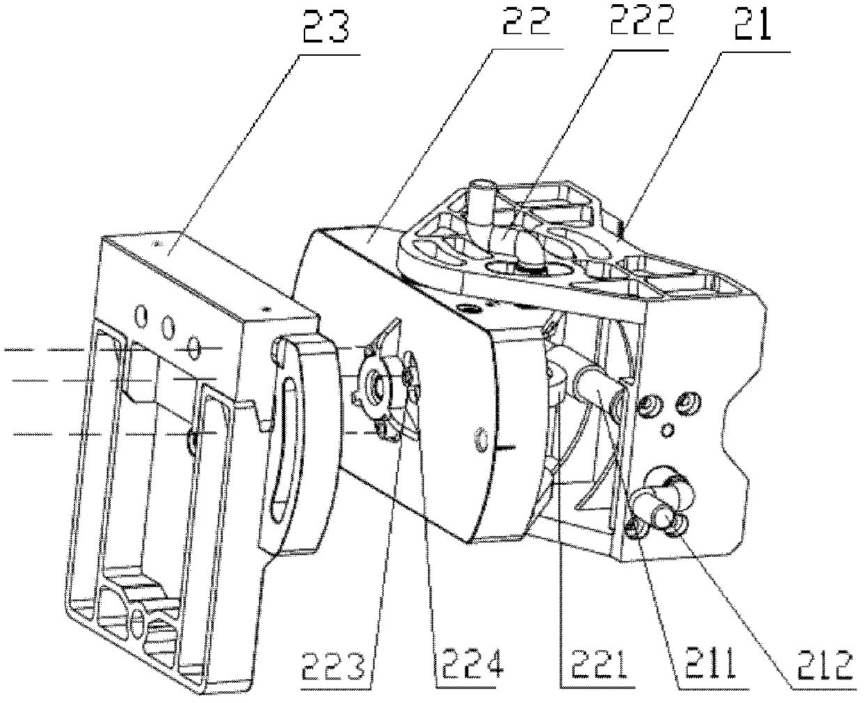
[0027] Please refer to figure 2 with image 3 , figure 2 It is a schematic structural diagram of a specific implementation of the microwave antenna adjusting device provided by the present invention, and the figure also shows the microwave antenna connected to the adjusting device; image 3 for figure 2 Schematic diagram of the middle adjustment device.

[0...


PUM


Abstract

An adjusting device of a microwave antenna comprises a supporting member hinged via a first hinge shaft and a mounting member for connecting the microwave antenna, wherein, the supporting member is equipped with a first worm. The adjusting device also comprises a first worm wheel cooperated with the first worm and fixed with the mounting member, the rotary axis of the first worm wheel is overlapped with the axis of the first hinge shaft, and the adjusting device also comprises a first driving device for driving the first worm. The adjusting device drives the mounting member to rotate relative to the supporting member via a worm and worm wheel mechanism so as to drive the microwave antenna to rotate connected with the mounting member, being simple in operation. And the worm and worm wheel mechanism is in linear transmission, the position adjustment of the microwave antenna is a linear adjustment, and the change of the microwave signal is continuous, has no jumping and is high in adjustment precision. In addition, the adjustment of the worm and worm wheel mechanism is stable, relative to a threaded rod driving in the prior art, the scheme does not employ a threaded rod, and does not need to process an excessive through hole, thereby avoiding a signal compulsion generated by fastening bolts at the two sides of the excessive through hole.

Description

Technical field [0001] The present invention relates to the field of communication technology, in particular to an adjusting device of a microwave antenna. Background technique [0002] In the field of communication technology, microwave is a commonly used point-to-point wireless transmission technology, which is generally used in scenarios where the location is relatively far away and it is inconvenient to lay cables. The signal radiated by the microwave is divided into a main lobe and a side lobe. To ensure the signal propagation quality between a pair of microwaves, it is required to adjust the position of the microwave antenna until the two main lobes of the microwave overlap each other in space. [0003] Please refer to figure 1 , figure 1 It is a schematic diagram of the structure of a microwave antenna and its adjusting device in the prior art. The adjustment device in the prior art includes a mounting member 12 for mounting a microwave antenna 14 and a support member 11 fi...

Claims


Application Information

Patent Timeline
IPC IPC(8): H01Q3/08
CPCH01Q1/125
Inventor 柯有和张伟王彬
Owner HUAWEI TECH CO LTD
Why Eureka
Try Eureka