Control device for an internal combustion engine
A control device and internal combustion engine technology, applied in engine control, internal combustion piston engine, electrical control, etc., can solve the problems of catalyst temperature drop, catalyst purification performance drop, etc., and achieve the effect of suppressing excessive temperature rise
- Summary
- Abstract
- Description
- Claims
- Application Information
AI Technical Summary
Problems solved by technology
Method used
Image

Examples
Embodiment approach 1
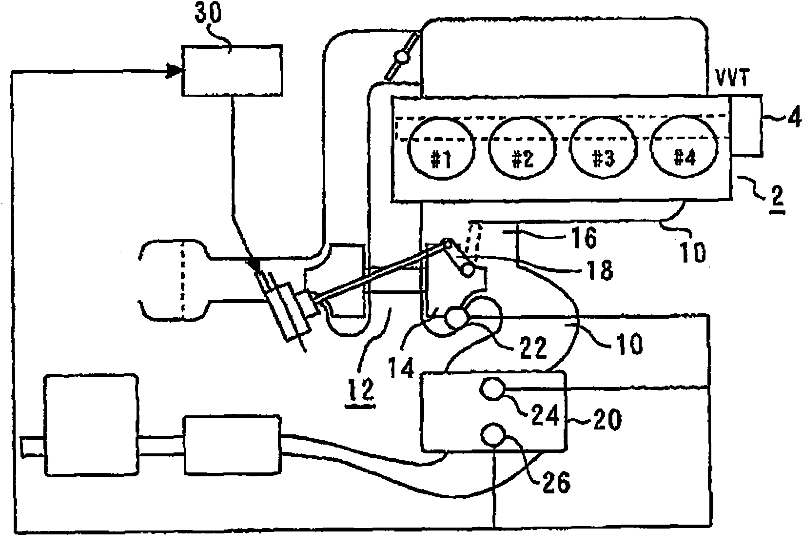
[0070] figure 1 It is a schematic diagram for explaining the overall configuration of the control device of the internal combustion engine and the system including its peripheral devices according to Embodiment 1 of the present invention. figure 1 The system has an internal combustion engine 2 . The internal combustion engine 2 has four cylinders #1 to #4. The internal combustion engine 2 is provided with a fuel injection valve for in-cylinder injection capable of directly injecting fuel into each cylinder.
[0071] The intake valve and the exhaust valve of each cylinder of the internal combustion engine 2 are provided with a variable valve mechanism (VVT) 4 for changing each valve opening characteristic (opening and closing timing, lift amount, etc.). The structure and operation of the VVT4 are well known, so detailed descriptions are omitted here.
[0072] An exhaust port of each cylinder is connected to an exhaust path 10 . An exhaust turbine 14 of a turbocharger 12 tha...
Embodiment approach 2
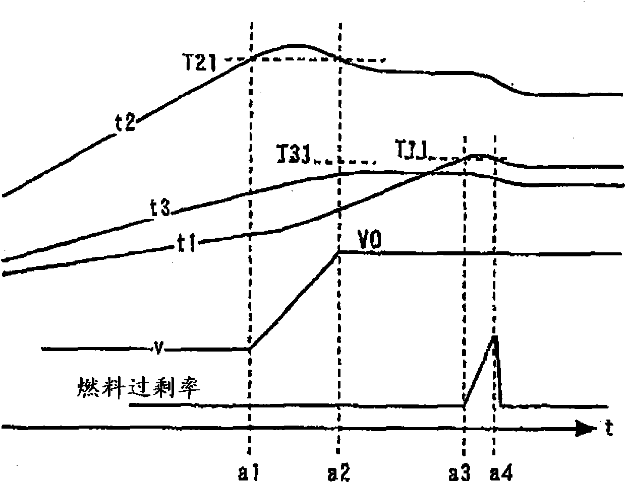
[0103] The system of Embodiment 2 has the same structure as the system of Embodiment 1. Figure 4 It is a timing chart for explaining the control content of Embodiment 2 of this invention. Figure 4 The time chart of is a control performed when not only the exhaust turbine 14 but also the entire exhaust system becomes excessively high in temperature.
[0104] Specifically, when the most downstream side and outlet temperature t1 of the exhaust system exceeds the high-temperature reference value T12 (exit high temperature reference value) at which the exhaust system may be damaged, it is conceivable that the entire purification catalyst 20 The temperature becomes high temperature. When the amount of blow-by air increases in this state, it is expected that the temperature of the purification catalyst 20 will further rise due to the reaction heat caused by the reaction of the leaked fresh air and unburned fuel, thereby damaging and deteriorating the purification catalyst 20 .
...
Embodiment approach 3
[0119] Figure 6 It is a timing chart for explaining the content of control in Embodiment 3 of the present invention. Figure 6 The content of the control is the control executed when the temperature of the purification catalyst 20 is at such a low temperature that the purification performance thereof may be degraded.
[0120] For example, when the inlet temperature of the purification catalyst 20 is near the lower limit of the active temperature range during a warm-up process, it is expected that the purification performance of the purification catalyst 20 will decrease. Furthermore, under such circumstances, it is conceivable that the temperature of the entire exhaust system including the exhaust turbine 14 drops. If the blow-by air amount is increased in such a low-temperature environment, it is expected that the temperature of the purification catalyst 20, especially the upstream part, will further drop and become lower due to the leaked low-temperature fresh air.
[012...
PUM
 Abstract
Description
Claims
Application Information
 - R&D
- Intellectual Property
- Life Sciences
- Materials
- Tech Scout
- Unparalleled Data Quality
- Higher Quality Content
- 60% Fewer Hallucinations
Browse by: Latest US Patents, China's latest patents, Technical Efficacy Thesaurus, Application Domain, Technology Topic, Popular Technical Reports.
© 2025 PatSnap. All rights reserved.Legal|Privacy policy|Modern Slavery Act Transparency Statement|Sitemap|About US| Contact US: help@patsnap.com