
Method and device for measuring spatial position between submarine pipeline flanges

A subsea pipeline and spatial location technology, which is applied to measuring devices, mechanical measuring devices, and mechanical devices, etc., can solve the problems of economic loss of flanges, high daily rates, delay in construction period, etc., so as to shorten the offshore construction time and simplify the operation. , the effect of high installation success rate

Inactive Publication Date: 2012-05-02
CHINA NAT OFFSHORE OIL CORP +1
View PDF2 Cites 10 Cited by
  • Summary
  • Abstract
  • Description
  • Claims
  • Application Information

AI Technical Summary

Problems solved by technology

In the existing submarine pipeline laying project, the measurement of the expansion bend of the sea pipe flange is just that the diver uses a steel ruler to measure the distance between the two flange surfaces (that is, the relative position of the two flange surfaces), and then begins to prefabricate the expansion on the deck. However, since the angle (relative orientation) and height (relative height difference) between the flange surface of the standpipe and the flange surface of the pipe are not measured, most of the prefabricated expansion bends cannot be installed smoothly, mainly the method of expansion bends The flange surface does not fit well with the flange surface of the standpipe and the flange surface of the flat pipe. The sealing effect of the flange connected in this way is poor, and leakage is prone to occur during the pressure test. In the end, it has to be reworked, which is time-consuming and labor-intensive, resulting in a serious delay in the construction period.
Due to extremely high day rates for offshore construction fleets, heavy economic losses can be caused simply by inaccurate flange measurements

Method used


Image

  • Method and device for measuring spatial position between submarine pipeline flanges
  • Method and device for measuring spatial position between submarine pipeline flanges
  • Method and device for measuring spatial position between submarine pipeline flanges

Examples


Embodiment Construction

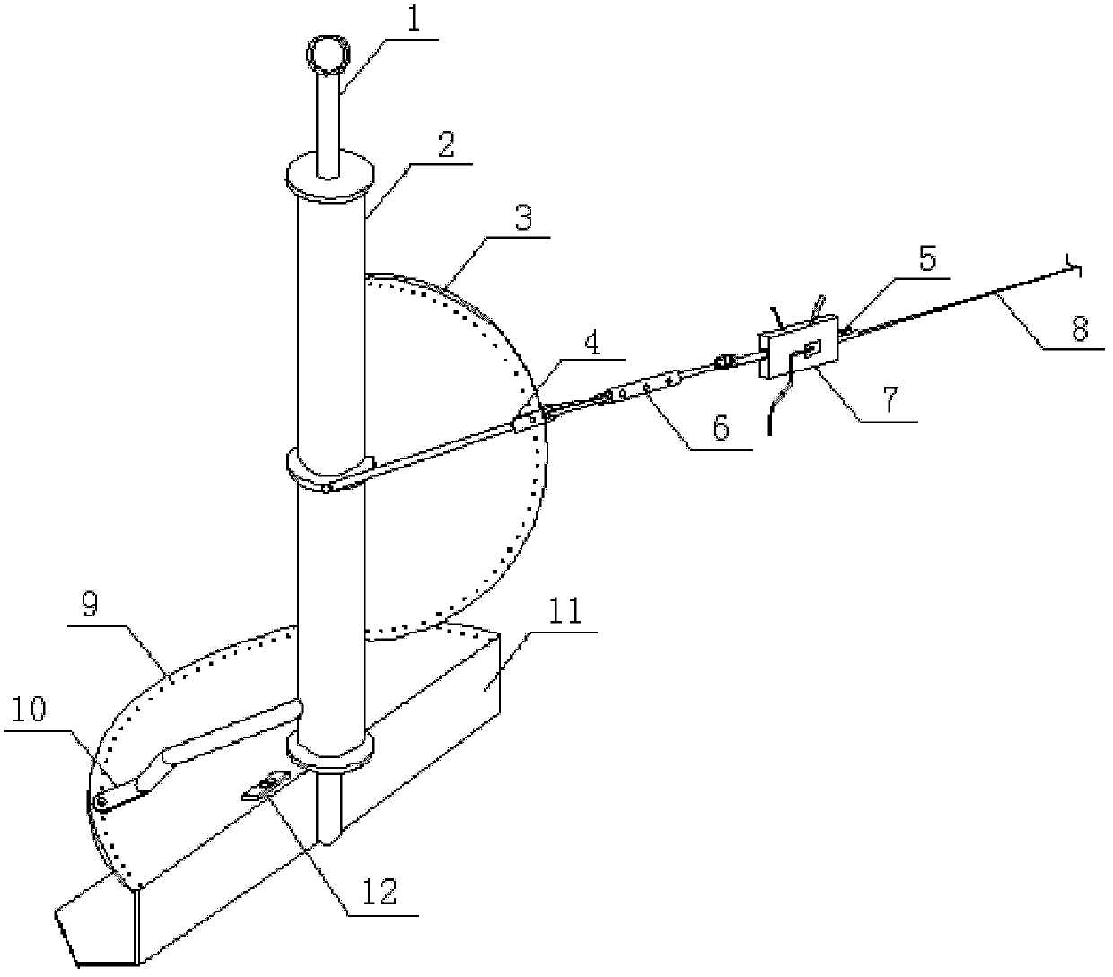
[0021] Such as figure 1 , figure 2 As shown, the method for measuring the spatial position of the flange of the submarine pipeline of the present invention, the first step is to install the spatial position measuring device A of the flange of the submarine pipeline at the flange B of the flat pipe end of the submarine pipeline, and install The space position measuring device A' of the flange of the submarine pipeline is installed at C; the second step is to connect the vertical distance between the space position measuring devices A and A' of the two submarine pipeline flanges through the distance measuring wire 8, the wire hoist 7 and the tensiometer 6. One end of the tensiometer 6 is connected with the vertical angle pointer of the submarine pipeline flange space position measuring device installed at a flange through a carabiner, and the other end is connected with one end of the wire hoist 7 through a snap ring. The other end of the gourd 7 is connected with one end of t...


PUM


Abstract

The invention discloses a method and a device for measuring a spatial position between submarine pipeline flanges. The method comprises the following steps of: arranging the devices for measuring the spatial position between the submarine pipeline flanges at the positions of a horizontal pipe end flange and a vertical pipe end flange of the submarine pipeline; connecting two vertical angle pointers between the two devices by using a distance measuring steel wire, a steel wire block and a tensionmeter; stringing the distance measuring steel wire by the steel wire block, wherein the sum of the lengths of the distance measuring steel wire, the two vertical angle pointers and the tensionmeter is the distance between the vertical pipe end flange and the horizontal pipe end flange of the submarine pipeline; reading indication of the horizontal angle pointers and the vertical angle pointers of the two devices; summarizing the data of the angles and the distances; arranging a vertical inclinometer rotation inner shaft, a horizontal inclinometer and a horizontal bubble instrument on a foundation of each device; arranging a vertical inclinometer rotation outer sleeve on the vertical inclinometer rotation inner shaft; arranging the horizontal angle pointer, a vertical inclinometer and the vertical angle pointer on the vertical inclinometer rotation outer sleeve; and accurately measuring the spatial position between the horizontal pipe end flange face and the vertical pipe end flange face of the submarine pipeline, so that an expansion bend can well coincide with the vertical pipe end flange face and the level pipe end flange face.

Description

technical field [0001] The invention relates to submarine pipeline laying technology and equipment, in particular to a method and device for measuring the space position of a flange of a submarine pipeline. Background technique [0002] With the rapid development of the offshore oil industry, more and more submarine pipelines will be laid on the seabed, which will inevitably lead to the connection of many seabed pipeline flange expansion bends. In the projects that have been completed and are about to be constructed, almost Each project has the connection of the flange expansion bend of the submarine pipeline (submarine pipeline for short). [0003] The so-called sea pipe flange expansion bend connection refers to the form of connection between the riser end flange and the flat pipe end flange of the submarine pipeline with an expansion bend. In the existing submarine pipeline laying project, the measurement of the expansion bend of the sea pipe flange is just that the dive...

Claims


Application Information

Patent Timeline
Patent Type & Authority Applications(China)
IPC IPC(8): G01B5/00G01B5/02G01B5/24
Inventor 朱绍华苗春生佟玉军陶杰桂津倪超魏行超
Owner CHINA NAT OFFSHORE OIL CORP
Learn More