Structure of variable oil pump

A kind of oil pump, variable technology, applied in the direction of pump, pump control, pump components, etc., can solve the problem of increased resistance to entry

Inactive Publication Date: 2012-05-02
HYUNDAI MOTOR CO LTD +1
View PDF6 Cites 0 Cited by
  • Summary
  • Abstract
  • Description
  • Claims
  • Application Information

AI Technical Summary

Problems solved by technology

[0009] However, as described above, the inlet 512 and the inlet space 518 are connected at a relatively small portion, such as the neck, and the inlet space 518 is connected to the side of the inlet 512, so t...

Method used


Image

  • Structure of variable oil pump
  • Structure of variable oil pump
  • Structure of variable oil pump

Examples


Embodiment Construction

[0023] Reference will now be made in detail to various embodiments of the invention, examples of which are illustrated in the accompanying drawings and described below. While the invention will be described in conjunction with exemplary embodiments, it will be understood that present description is not intended to limit the invention to those exemplary embodiments. On the contrary, the invention is intended to cover not only the exemplary embodiments, but also various alternatives, modifications, equivalents and other embodiments, which may be included within the spirit and scope of the invention as defined by the appended claims .

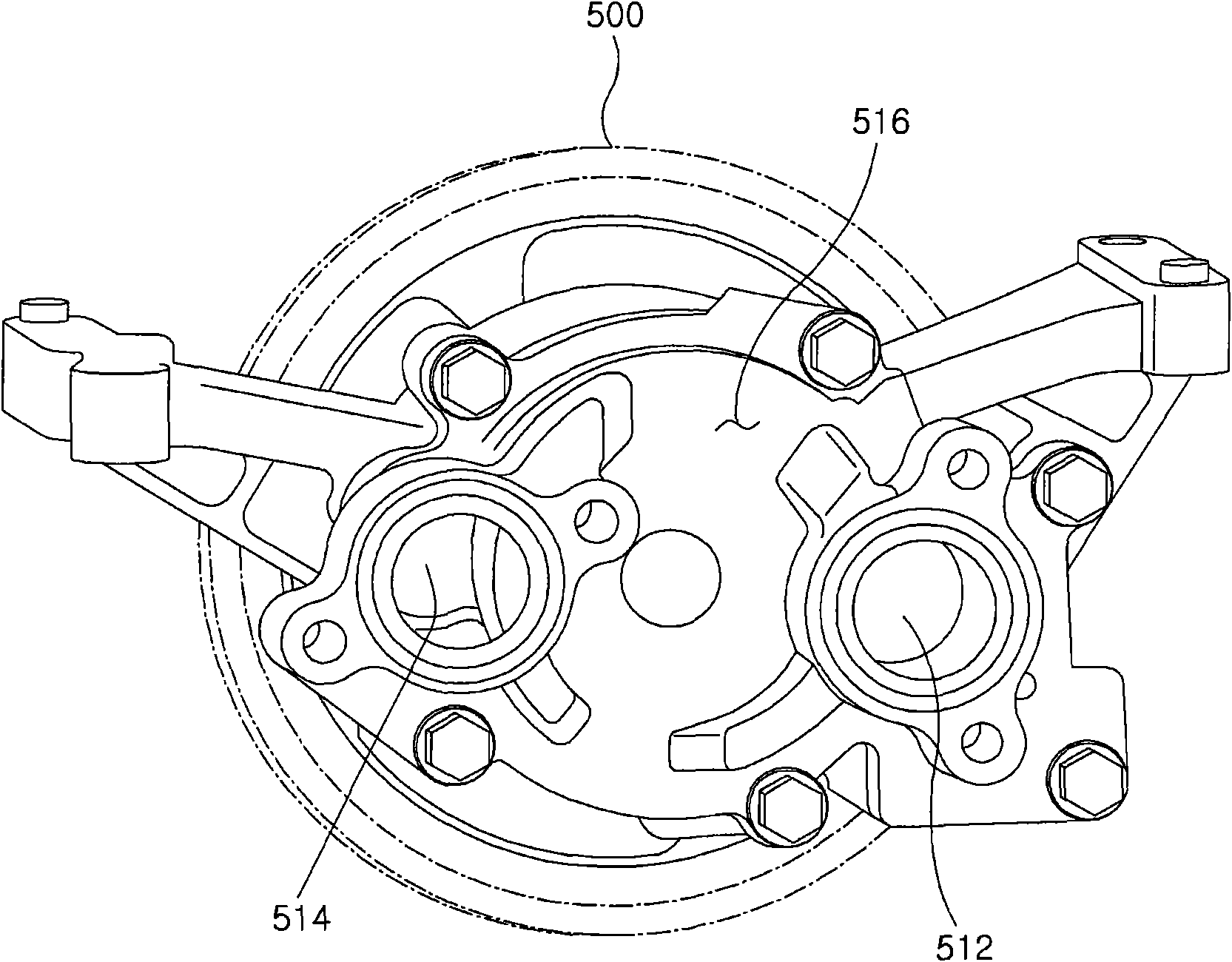
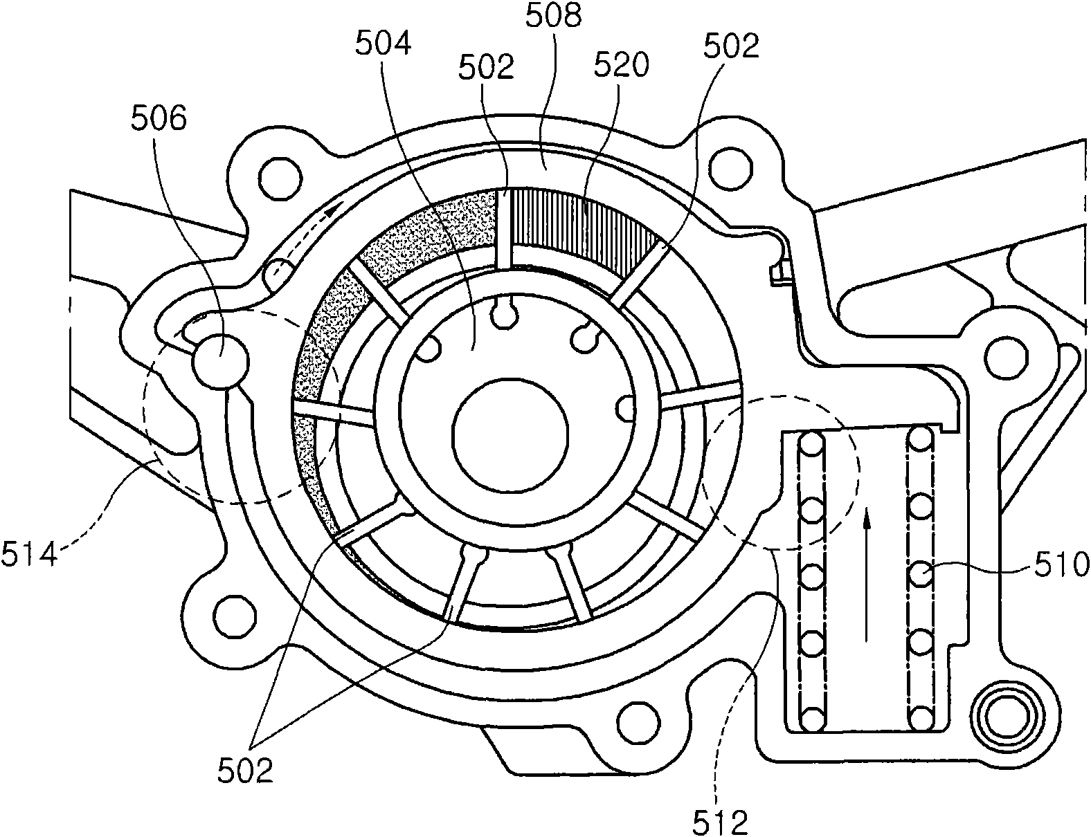
[0024] refer to Figure 5 with Image 6 , the variable oil pump according to various embodiments of the present invention may include: an inlet 1 connected to supply oil into a tank of the variable oil pump, an arc-shaped entry space 5, and a buffer space (buffer space) 7, the arc-shaped A shaped inlet space 5 is formed in the case so as to be ...


PUM


Abstract

A variable oil pump includes an inlet connected to supply oil into the housing of the variable oil pump an arc-shaped intake space formed in the housing to be connected to a pumping space between veins mounted on a rotor in the variable oil pump; and a buffer space having a large cross-sectional area than inlet and connected with inlet and intake space, such that it is possible to reduce pulse noise generated in the variable oil pump by reducing intake resistance and vortex which are generated in sucking oil at the intake side of the variable oil pump.

Description

[0001] Cross References to Related Applications [0002] This application claims priority from Korean Patent Application No. 10-2010-0094806 filed on Sep. 29, 2010, the entire contents of which are hereby incorporated by reference for all purposes. technical field [0003] The present invention relates to a variable oil pump, and more particularly, to a passage structure through which oil flows into the variable oil pump, which improves the flow rate of the discharge by adjusting the flow rate of the discharge according to the change of the number of revolutions of the engine. The fuel efficiency of the vehicle's engine and by utilizing the power provided from the engine to prevent unnecessary waste of energy when pumping oil. Background technique [0004] figure 1 with figure 2 The external shape and internal structure of a variable oil pump in the related art are shown, including: a driving gear 500 receiving power from an engine; a rotor 504 rotating by torque from the...

Claims


Application Information

Patent Timeline
IPC IPC(8): F04C2/344
CPCF04C14/226F04C2/086F04C15/0049F04C2/3441
Inventor 林在泌
Owner HYUNDAI MOTOR CO LTD
Why Eureka
Try Eureka