
Electric drill with driving mode switching

A driving mode and electric drill technology, which is applied in the manufacture of tools and portable mobile devices, etc., can solve the problems of many parts in the transmission link of mode switching, large running resistance, and cumulative error affecting performance, etc.

Active Publication Date: 2012-05-02
NANJING JIUCHI ELECTROMECHANICAL IND
View PDF11 Cites 14 Cited by
  • Summary
  • Abstract
  • Description
  • Claims
  • Application Information

AI Technical Summary

Problems solved by technology

[0007] It can be seen that the typical structure of the electric drill with the driving mode switching function either has the problem of a large number of parts in the mode switching transmission link, which not only easily affects its performance due to accumulated errors, but also is not easy to manufacture and assemble; or the running resistance is relatively large

Method used


Image

  • Electric drill with driving mode switching
  • Electric drill with driving mode switching
  • Electric drill with driving mode switching

Examples


Embodiment 1

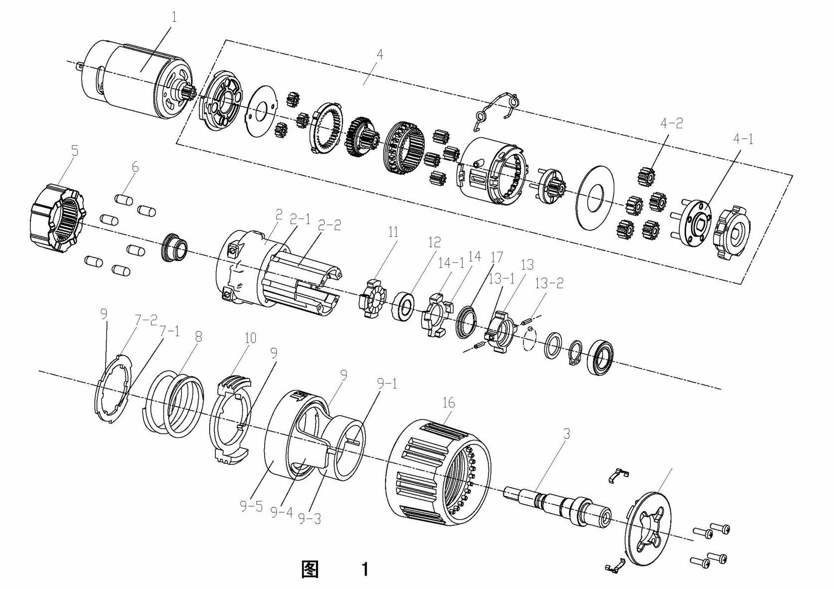
[0018] This embodiment has an electric drill with driving mode switching such as figure 1As shown, it includes a motor 1 placed inside the casing, a rotatable function switching cup 9 and a torque regulating cup 16 set outside the casing. The motor 1 is connected to the output shaft 3 through the two-stage planetary gear reduction mechanism 4 installed in the gearbox 2, and the output shaft 3 is engaged with the second stage of the inner ring gear 5 through the special-shaped hole in the center of the planetary gear train ring 4-1. The shaft centers of the planetary gears 4-2 form a synchronous rotation relationship, and the static impact ring 11 with end teeth and the fixed block 14 with evenly spaced end bosses 14-1 are fixedly installed in the gearbox 2. The function switching cup 9 is composed of a gear ring 9-5 and a ring constraint ring 9-3 connected by two side wing plates 9-4 extending towards the output shaft direction. The inner hole of the gear ring 9-5 has a 7 The...


PUM


Abstract

The invention relates to an electric drill with driving mode switching, belonging to the technical field of electric tools. The electric drill comprises a motor, a function switching cup and a torque regulating cup, wherein the motor is connected with an output shaft through a reducing mechanism in transmission mode. The invention is improved in the following ways: the other end of a conjunction piece abuts against one end of a locking ring; the other end of the locking ring is connected with an axial pressure regulating mechanism driven by the torque regulating cup; when the function switching cup is in a first switching position, contrate teeth of the movable and static impact rings are separated, and the locking ring forms axial constraint on the conjunction piece; when the function switching cup is in a second switching position, the contrate teeth of the movable and static impact rings remain separated, and the locking ring loses axial constraint on the conjunction piece; and when the function switching cup is in a third switching position, the contrate teeth of the movable and static impact rings abuts against each other, and the locking ring forms axial constraint on the conjunction piece. The invention can lower the manufacturing and assembly cost, is beneficial to avoiding poor quality caused by accumulated tolerance, and is easier to operate.

Description

technical field [0001] The invention relates to an electric drill, in particular to an electric drill with driving mode switching, and belongs to the technical field of electric tools. Background technique [0002] A hand-held electric drill capable of drilling, screwing, and impact mode switching is a commonly used electric tool that has been widely used. [0003] The early US patent No. US6142242 discloses the following technical solution of this electric drill (note: for ease of interpretation, the part numbers corresponding to the drawings of the US6142242 embodiment are in parentheses in this paragraph): a percussion drill, including a motor (3 ) of the main body shell (2); the planetary gear reduction mechanism (10) installed in the main body shell, the planetary gear reduction mechanism is provided with a rotatable internal gear (13), an input end that can be installed on the motor, and a A cam mechanism (17, 18, 19) that transmits rotational power to the output of t...

Claims


Application Information

Patent Timeline
IPC IPC(8): B25F3/00
Inventor 吹拔正敏陆传洋
Owner NANJING JIUCHI ELECTROMECHANICAL IND
Learn More