
External clock synchronization circuit of switching power supply

A switching power supply and external synchronization technology, which is applied in the direction of electrical components, automatic power control, output power conversion devices, etc., can solve the problems of frequency jitter, circuit complexity, and long time for external synchronization of clocks, etc., to achieve accurate transmission, circuit The effect of simple structure and shortened external synchronization time

Active Publication Date: 2012-04-25
深圳德信微电子有限公司
View PDF3 Cites 9 Cited by
  • Summary
  • Abstract
  • Description
  • Claims
  • Application Information

AI Technical Summary

Problems solved by technology

[0004] Since the phase-locked loop technology is used to realize the clock external synchronization function, it is necessary to consider the loop stability of the phase-locked loop, the circuit is relatively complicated, and it takes a long time to lock the frequency, and the time for the entire clock external synchronization is relatively long. In addition, due to the lock Due to the non-ideal characteristics of the phase loop, there is frequency jitter, so it cannot accurately synchronize the external clock signal

Method used


Image

  • External clock synchronization circuit of switching power supply
  • External clock synchronization circuit of switching power supply
  • External clock synchronization circuit of switching power supply

Examples


Embodiment Construction

[0021] The present invention is described in further detail below in conjunction with accompanying drawing.

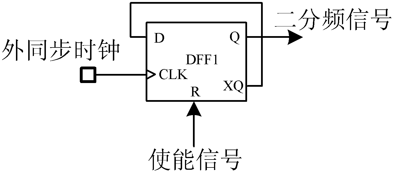
[0022] refer to figure 1 , The clock external synchronization circuit of the present invention includes a frequency division circuit 1 , a frequency upper limit detection circuit 2 , a frequency lower limit detection circuit 3 , an external synchronization stop detection circuit 4 and a frequency selection circuit 5 . After the external synchronous clock is divided by 2 into a square wave signal with a duty ratio of 50%, it is connected to the frequency lower limit detection circuit 2 and the frequency upper limit detection circuit 3 to detect whether the frequency of the external synchronous clock is at the preset value interval; the input terminal of the external synchronous stop detection circuit 4 is connected to the external synchronous clock, and the control signal k3 output by the output terminal is connected to the frequency lower limit detection circuit 3, so ...


PUM


Abstract

The invention discloses an external clock synchronization circuit of a switching power supply. In the prior art, a circuit structure is complex, external synchronization time is long and frequency jitter exists. By using the external clock synchronization circuit of the switching power supply, the above disadvantages can be overcome. The circuit comprises: a frequency-halving circuit, a frequency cap detection circuit, a lower limit frequency detection circuit, an external synchronization stopping detection circuit and a frequency selection circuit. An external synchronous clock is connected to the lower limit frequency detection circuit and the frequency cap detection circuit through the frequency-halving circuit so as to detect whether the external synchronous clock frequency is in a preset numerical interval. The lower limit frequency detection circuit is connected with the synchronization stopping detection circuit so as to determine whether the external synchronous clock is removed. Control signals output by the lower limit frequency detection circuit and the frequency cap detection circuit are connected to the frequency selection circuit so that the frequency selection circuit is controlled to select one from an internal clock and the external synchronous clock to output so as to be taken as a working clock of the switching power supply. A circuit structure is simple. The external clock can be rapidly and accurately synchronized and the external clock synchronization circuit of the invention can be applied in various kinds of the switching power supplies.

Description

technical field [0001] The invention belongs to the technical field of electronic circuits, and relates to an analog integrated circuit, in particular to an external clock synchronization circuit of a switching power supply. Background technique [0002] Switching power supply is widely used in various electronic devices due to its light weight, small size, high conversion efficiency and many other advantages. However, since it works at a certain frequency, frequency-related problems such as electromagnetic interference and switching noise are unavoidable. In particular, the problem of difference frequency noise in parallel or series systems of multiple switching power supplies with close frequencies is particularly prominent. The operating clock of the switching power supply is generally provided by an internal oscillator, but because the frequency provided internally is fixed, it cannot be changed at any time to adapt to different application environments. Therefore, for...

Claims


Application Information

Patent Timeline
Patent Type & Authority Applications(China)
IPC IPC(8): H03L7/10H02M1/00
Inventor 来新泉刘雨鑫叶强毛翔宇李演明
Owner 深圳德信微电子有限公司
Learn More