Eureka AIR delivers breakthrough ideas for toughest innovation challenges, trusted by R&D personnel around the world.

Acoustic emission signal sensing system based on matching-type fiber Bragg grating (FBG)

A technology of acoustic emission signal and fiber Bragg, which is applied in the use of acoustic emission technology for material analysis, the use of wave/particle radiation, and the measurement of ultrasonic/acoustic/infrasonic waves, etc. System and other problems, to achieve the effect of strong anti-electronic interference, high detection accuracy and low noise

Inactive Publication Date: 2012-04-25
BEIHANG UNIV +1
View PDF6 Cites 27 Cited by
  • Summary
  • Abstract
  • Description
  • Claims
  • Application Information

AI Technical Summary

Problems solved by technology

[0004] Existing fiber grating sensing systems, such as Chinese patents ZL201010273400.1 "A Transformer Internal Temperature Detection System Based on Fiber Bragg Grating", ZL200910024155.8 "A Fiber Bragg Grating Stress Monitoring System", etc., all use fiber Bragg grating as a temperature sensor. and stress sensors; the existing acoustic emission detection systems such as Chinese patent CN2724019Y "an earthquake and landslide monitoring system based on acoustic emission" and other acoustic emission detection systems used in the acoustic emission detection system are based on piezoelectric ceramic materials. There is no relatively mature sensor system for detecting acoustic emission signals with fiber gratings

Method used


Image

  • Acoustic emission signal sensing system based on matching-type fiber Bragg grating (FBG)
  • Acoustic emission signal sensing system based on matching-type fiber Bragg grating (FBG)
  • Acoustic emission signal sensing system based on matching-type fiber Bragg grating (FBG)

Examples


Embodiment Construction

[0017] Specific embodiments of the present invention will be described below in conjunction with the accompanying drawings, so as to better understand the present invention. It should be noted that in the following description, when detailed descriptions of known functions and designs may dilute the main content of the present invention, these descriptions will be omitted here.

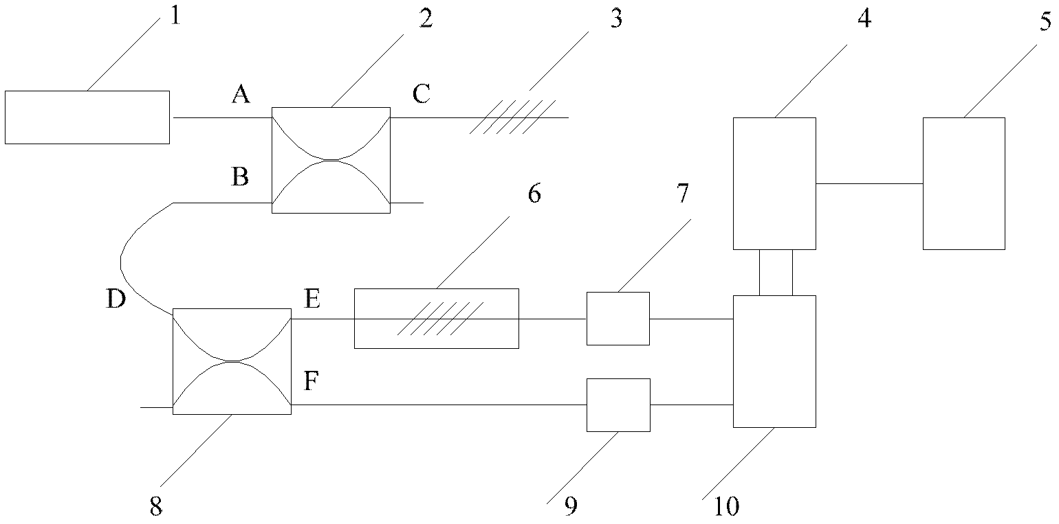
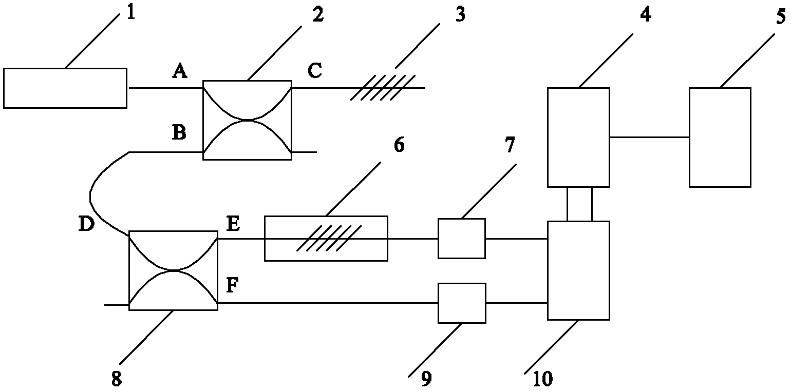
[0018] Such as figure 1 As shown, the matching fiber Bragg grating acoustic emission signal sensing system of the present invention includes: broadband light source 1, first and second fiber couplers 2, 8, fiber Bragg grating 3, tunable fiber Bragg grating filter 6 , the first and second photodetection circuits 7, 9, the analog-to-digital conversion circuit 10, and the FBGA 4; wherein, the A port and the C port of the first fiber coupler 2 are respectively connected to the broadband light source 1 and the fiber Bragg grating 3, and the B port is connected to The D port of the second fiber coupler 8; ...


PUM

PropertyMeasurementUnit
Center wavelengthaaaaaaaaaa
Bandwidthaaaaaaaaaa

Abstract

The invention provides an acoustic emission signal sensing system based on matching-type fiber Bragg grating (FBG), which aims to overcome limitation of the prior art and introduce an FBG sensor into the acoustic emission detection field. The acoustic emission signal sensing system comprises a broadband light source, a first fiber coupler, a second fiber coupler, the FBG, a tunable FBG filter, a first photoelectric detection circuit, a second photoelectric detection circuit, an analog-to-digital conversion circuit, an FBG array (FBGA) and a computer. The acoustic emission signal sensing system is mainly applied to structural safety monitoring of an aerospace plane and damage detection of important components, and has the advantages of high sensitivity, high response speed, long transmission distance and strong resistance to electronic interference; and compared with the power-type FBG acoustic emission sensing system, the acoustic emission signal sensing system based on the matching-type FBG provided by the invention has the beneficial effects that wavelength shift information is demodulated by a matching grating method so as to obtain information of an original acoustic emission wave, the detection object is optical wavelength rather than optical power, and optical wavelength information is not affected by optical power loss during the optical transmission process, thus the detection precision is higher, the resolution power is higher and the noise is smaller.

Description

technical field [0001] The invention belongs to the technical field of acoustic emission detection, in particular to an acoustic emission signal sensing system based on a matching fiber Bragg grating. Background technique [0002] Acoustic emission is a new technology that is widely used in modern nondestructive testing and structural material research. Its principle is that the material of the stressed component will release plastic strain energy during the initiation and expansion of damage defects, and the strain energy is in the form of stress waves. Outward propagation expansion, this phenomenon is called the acoustic emission phenomenon. Acoustic emission technology is the use of high-sensitivity acoustic emission sensors installed on the surface of the stressed member to form a certain number of sensor arrays to receive and collect acoustic emission signals from material defects in real time, and then through the identification, judgment and analysis of these acoustic...

Claims


Application Information

Patent Timeline
IPC IPC(8): G01N29/24G01N29/14G01H9/00
Inventor 魏鹏李宁刘奇孙志平梅盛开李成贵涂万里
Owner BEIHANG UNIV
Why Eureka
Eureka Blog
Learn More