High-temperature and high-pressure steam pressure reducing ball valve and production technology thereof

A high-temperature, high-pressure, ball valve technology, applied in metal material coating process, valve details, valve devices, etc., can solve the problems that single-seat control valves cannot meet the demand, are not resistant to erosion, and are easy to be damaged, so as to avoid local embrittlement , prolong the service life and reduce the flow rate

Active Publication Date: 2012-04-25
四川苏克流体控制设备有限公司
View PDF6 Cites 2 Cited by
  • Summary
  • Abstract
  • Description
  • Claims
  • Application Information

AI Technical Summary

Problems solved by technology

[0002] Most of the existing high-temperature and high-pressure steam valves are single-seat control valves. The use of single-seat control valves has a history of hundreds of years. Due to the limitation of metal material properties, the existing single-seat control valve is increasingly unable to meet the needs of harsh working conditions such as high temperature and high pressure steam
As a type of single-seat regulating valve, the single-seat pressure reducing valve is not resistant to erosion and cavitation. Therefore, the single-seat pressure reducing valve is easy to be damaged or even penetrated in the high-temperature and high-pressure steam environment for a long time.

Method used


Image

  • High-temperature and high-pressure steam pressure reducing ball valve and production technology thereof
  • High-temperature and high-pressure steam pressure reducing ball valve and production technology thereof

Examples


Embodiment

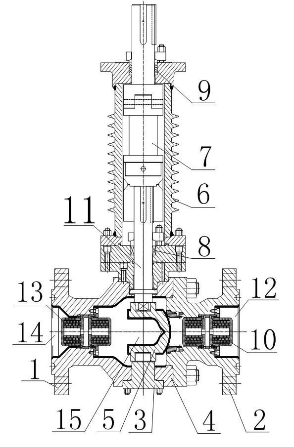
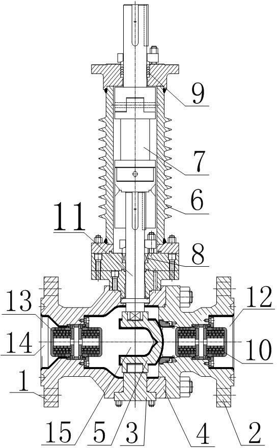
[0021] Such as figure 1 As shown, the high-temperature and high-pressure steam pressure-reducing ball valve includes a valve body 1, a V-shaped ball 5 and a left body 2 connected to the valve body 1. The valve body 1 and the left body 2 form a ball cavity, and the valve body 1 is provided with an outlet 14 and Connect the inner cavity of the outlet 14 and the sphere cavity, the left body 2 is provided with the inlet 12 and the inner cavity connected with the inlet 12 and the spheroid cavity, the inner cavity of the left body 2 is provided with a first pressure reducer 10, the valve body 1 A second pressure reducer 13 is provided in the inner cavity, wherein the first pressure reducer 10 and the second pressure reducer 13 are made of ceramic materials with a cage-type porous structure, that is, the first pressure reducer 10 and the second pressure reducer The side walls of both devices 13 form a structure with multi-layer sleeves, and each layer of sleeves is provided with a pl...


PUM


Abstract

The invention discloses a high-temperature and high-pressure steam pressure reducing ball valve, which comprises a valve body, a V-shaped ball body and a left body, wherein the valve body and the left body form a ball body cavity; the valve body is provided with an outlet; the left body is provided with an inlet; a first pressure reducer is arranged in the inner cavity of the left body; a valve seat connected with the left body is arranged between the inner cavity of the left body and the ball body cavity; and the V-shaped ball body is arranged in the ball body cavity and in fit contact with a hard seal of the valve seat. The upper and lower ends of the V-shaped ball body are respectively connected with an upper valve rod and a lower valve rod, and a runner is formed in the V-shaped ball body. The valve body, the left body, the valve seat, the ball body, the upper valve rod and the lower valve rod are all made of metal materials; and the valve body, the valve seat and the ball body of the pressure reducing ball valve and the end face in contact with a medium flowing through the pressure reducing ball valve are respectively coated with abrasion-resistant anticorrosive layers. The invention also discloses a production technology for the high-temperature and high-pressure steam pressure reducing ball valve. The internal sealing performance, the pressure reducing performance and the service life of the pressure reducing ball valve can be ensured under the severe working conditions of high abrasion, high corrosion, high temperature, high pressure, high flow rate, gas erosion and the like.

Description

technical field [0001] The invention relates to a ball valve, in particular to a high-temperature, high-pressure steam pressure-reducing ball valve and a production process thereof. Background technique [0002] Most of the existing high-temperature and high-pressure steam valves are single-seat control valves. The use of single-seat control valves has a history of hundreds of years. Due to the limitation of metal material properties, the existing single-seat control valve is increasingly unable to meet the needs of harsh working conditions such as high temperature and high pressure steam. As a type of single-seat regulating valve, the single-seat pressure reducing valve is not resistant to erosion and cavitation. Therefore, the single-seat pressure reducing valve is easily damaged or even broken through after long-term use in a high-temperature and high-pressure steam environment. In order to overcome the defects of the existing single-seat pressure reducing valve, it is p...

Claims


Application Information

Patent Timeline
IPC IPC(8): F16K5/06F16K5/08F16K27/06F16K41/02F16K47/04C23C4/10C23C4/11C23C4/134
Inventor 张道军
Owner 四川苏克流体控制设备有限公司
Why Eureka
Try Eureka