
Waste heat power generation device capable of obtaining waste gas in multistage from sintering machine and cooling machine in steel plant

A technology of waste heat power generation and sintering machine, which is applied in the direction of steam engine installation, waste heat treatment, machine/engine, etc. It can solve problems such as not considering the composition of sintering machine flue gas, affecting boiler operation and service life, and pipe perforation, so as to avoid low temperature Acid dew point corrosion problem, save civil engineering amount, and reduce weight

Active Publication Date: 2013-06-12
大连九五高科新能源发展有限公司
View PDF2 Cites 0 Cited by
  • Summary
  • Abstract
  • Description
  • Claims
  • Application Information

AI Technical Summary

Problems solved by technology

This patent does not take into account that the composition of the flue gas at the tail of the sintering machine is relatively complex, containing impurities such as SOx, NOx and dust
If low-pressure parameters are used to recover this part of heat, low-temperature acid dew point corrosion will inevitably occur on the heating surface of the boiler, which will directly affect the operation and service life of the boiler. In severe cases, the tube will be perforated and the furnace will be shut down.

Method used


Image

  • Waste heat power generation device capable of obtaining waste gas in multistage from sintering machine and cooling machine in steel plant
  • Waste heat power generation device capable of obtaining waste gas in multistage from sintering machine and cooling machine in steel plant
  • Waste heat power generation device capable of obtaining waste gas in multistage from sintering machine and cooling machine in steel plant

Examples


Embodiment Construction

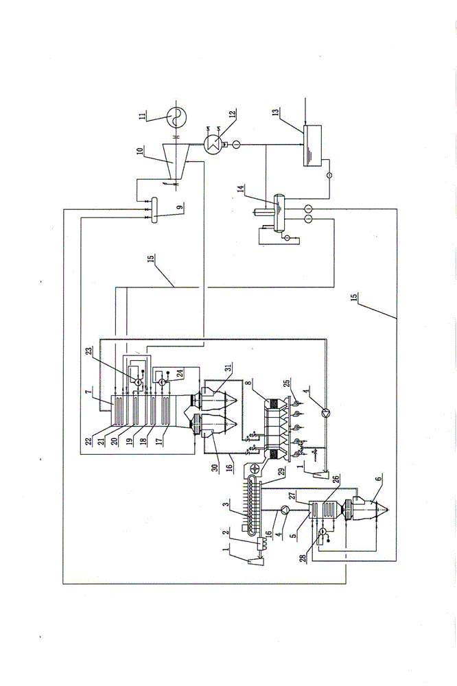
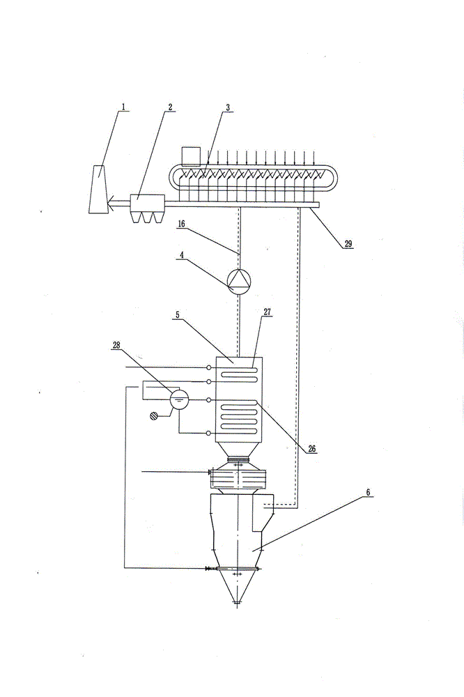
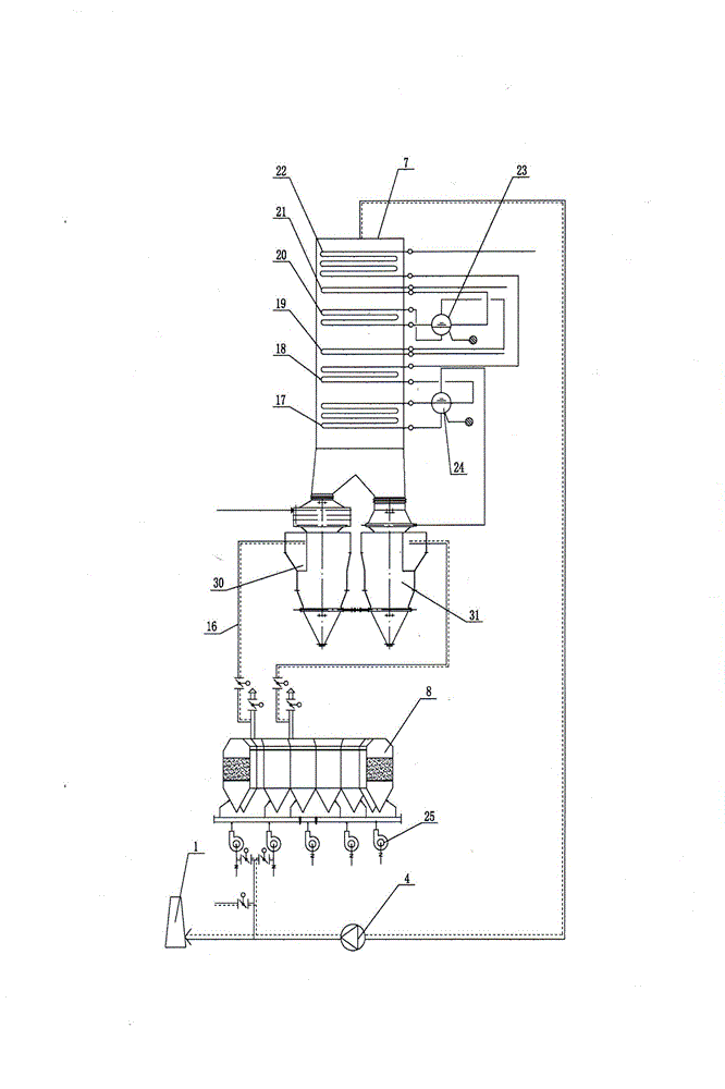
[0021] exist figure 1 and figure 2 In the schematic diagram of the front view of the sintering machine and cooler multi-stage exhaust gas waste heat power generation device shown in the iron and steel plant, the sintering machine components include the sintering machine 3, the tail main flue 29, the electrostatic precipitator 2 and the chimney 1, all of which are for existing technology. The above sintering integrated waste heat recovery device mainly includes a cyclone superheater 6, a sintering machine waste heat boiler 5 and pipelines, wherein the cyclone superheater 6 and sintering machine waste heat boiler 5 are arranged in an integrated form and share a common foundation. The cyclone superheater 6 adopts the structure of the Chinese utility model patent No. ZL2010 2 0554915.4. The above-mentioned equipment has the following connections: the main flue 29 at the tail of the sintering machine is connected to the upper side opening of the cyclone superheater 6, the upper ...


PUM


Abstract

The invention discloses a waste heat power generation device capable of obtaining waste gas in multistage from a sintering machine and a cooling machine in a steel plant. The waste heat power generation device disclosed by the invention mainly comprises a sintering machine assembly and a sintering integrated waste heat recovering device, a cooling machine assembly and a cooling integrated waste heat recovering device, as well as a condensed water tank, a condenser, a deaerator, a feed water treatment device, a turbine, a power generator and other supporting facilities, wherein the sintering machine assembly comprises a sintering machine, a tail-part main flue, an electric dust collector and a chimney; the sintering integrated waste heat recovering device mainly comprises a cyclone overheater, a sintering machine waste heat boiler and a pipeline; the cooling machine assembly comprises a cooling machine, an air blower and a chimney; and the cooling integrated waste heat recovering device mainly comprises two cyclone overheaters, a cooling machine waste heat boiler and a smoke and air pipeline. According to the invention, the waste gas generated by the sintering machine and the cooling machine in the steel plant can be obtained in multistage according to different temperatures, so that the investment cost of devices can be reduced, the waste heat power generation capacity is increased, and the service life of equipment is prolonged.

Description

technical field [0001] The invention relates to a waste heat power generation device, in particular to a waste heat power generation device which utilizes sintering and cooling machines in iron and steel plants to extract waste gas waste heat in multiple stages. Background technique [0002] The energy consumption of the sintering process in iron and steel enterprises accounts for 10% to 20% of the total energy consumption, ranking second only to the ironmaking process. At present, the energy consumption of the sintering process in China is relatively high, and the average energy consumption per ton of sintering ore is more than 19% higher than that of foreign advanced indicators. One of the main reasons is that the recovery rate of waste heat resources in the sintering process is low. At present, some enterprises in my country use the waste heat of coolers to produce steam to drive steam turbines to generate electricity. The technology they generally adopt is to set three ...

Claims


Application Information

Patent Timeline
Patent Type & Authority Patents(China)
IPC IPC(8): F01K11/02F01D15/10F27D17/00
CPCY02P10/25Y02P80/15
Inventor 唐金泉金万金孙明朗刘峰
Owner 大连九五高科新能源发展有限公司
Learn More