
CO2 circulating and coal gas compensation combustion type power generation method by sintered waste heat

A waste heat power generation and coal gas technology, which is applied in the field of sintering waste heat utilization, can solve problems affecting steam parameters and power generation, difficult control, flue gas temperature fluctuations of waste heat boilers, etc., and achieve considerable economic benefits and improve the effect of waste heat power generation capacity

Active Publication Date: 2011-01-26
SHOUGANG CORPORATION +1
View PDF0 Cites 0 Cited by
  • Summary
  • Abstract
  • Description
  • Claims
  • Application Information

AI Technical Summary

Problems solved by technology

[0005] The main problem of the above method is that it can improve the recovery rate of waste heat, but it cannot fundamentally solve the problem of improving the steam parameters of power generation. The existing sintered ring cold waste heat power generation can only achieve low or medium low temperature waste heat In the power generation system, waste heat power generation capacity is limited; and when the temperature of the sinter fluctuates, it will cause fluctuations in the temperature of the flue gas entering the waste heat boiler, which will affect the steam parameters and power generation, which is difficult to control in practice

Method used


Image

  • CO2 circulating and coal gas compensation combustion type power generation method by sintered waste heat
  • CO2 circulating and coal gas compensation combustion type power generation method by sintered waste heat

Examples


Embodiment Construction

[0016] The present invention will be further described below in conjunction with the accompanying drawings.

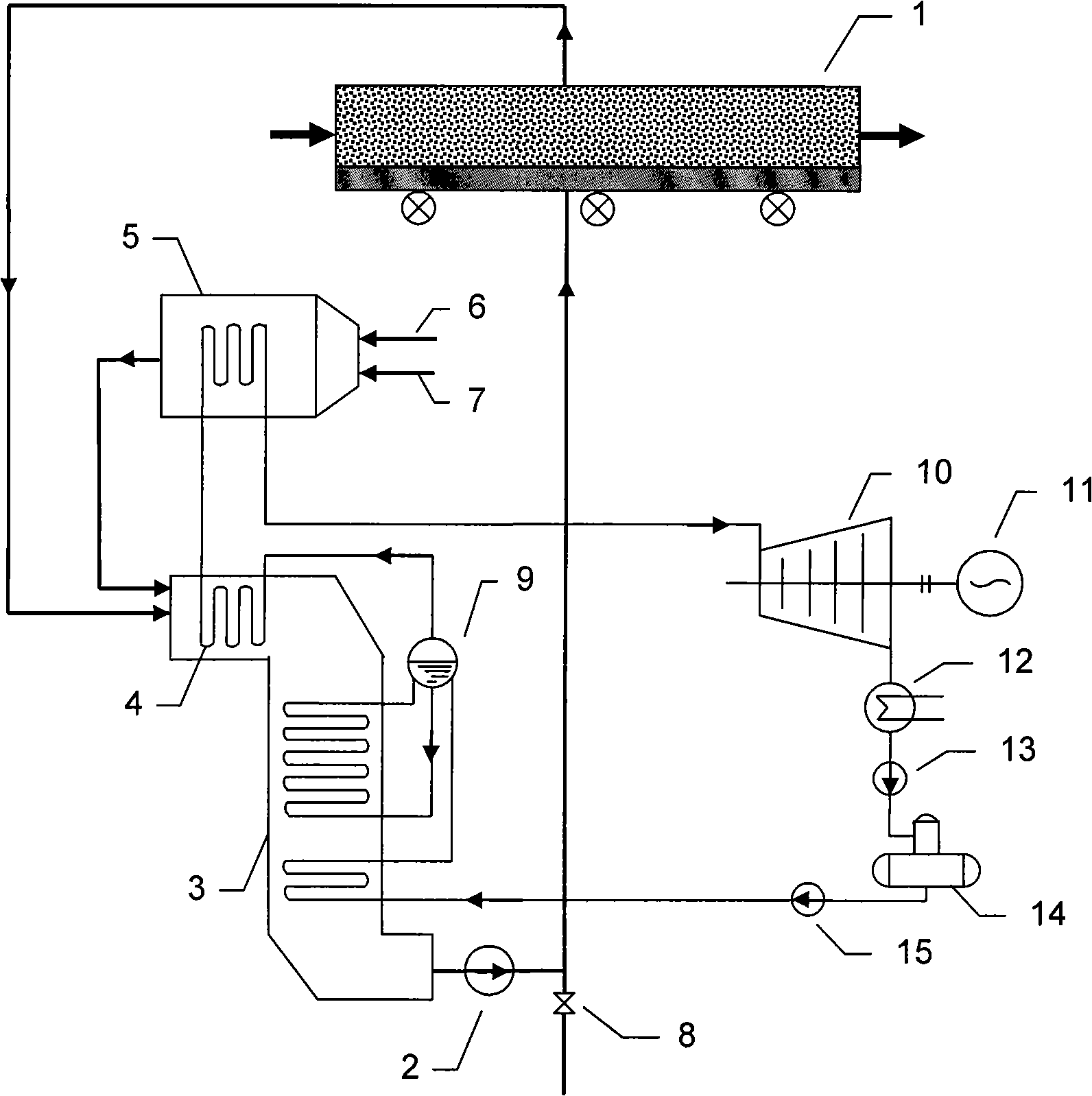
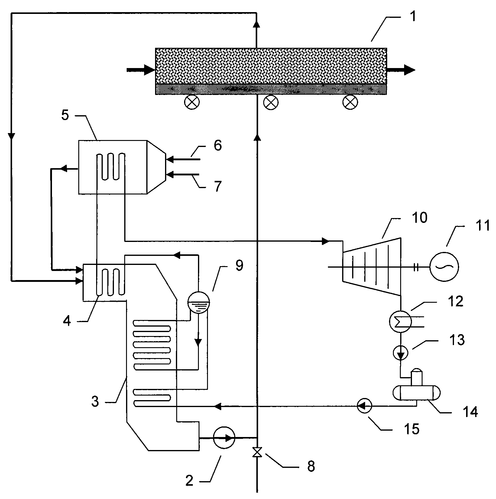
[0017] figure 1 It is a diagram of the sintering ring cold waste heat power generation system using converter gas supplementary combustion and its combustion flue gas as the cooling medium. Such as figure 1 As shown, there are mainly two cycles in the system: one is the cooling gas cycle; the other is the steam system cycle. Cooling gas circulation: using flue gas after converter gas combustion as the medium, high CO 2 Concentrated flue gas first absorbs the sensible heat of sintering ore in sintering ring cooler 1, and the temperature rises above 500°C, then enters waste heat boiler 3 to release heat, drops to about 150°C at the boiler outlet, and is sent back to the sintering ring by fan 2 Cold machine 1 can be regarded as a closed cycle without considering air leakage and supplementary converter gas combustion. Steam system cycle: the outlet steam of the low-tem...


PUM


Abstract

A CO2 circulation and gas complementary combustion type sintering waste heat power generation method belongs to the sintering waste heat utilization field. The method is characterized in that, CO2 is used for replacing air to be used as a cooling medium of sinter, the specific heat of the CO2 is greater than the air, the CO2 can more efficiently recover sensible heat of the sinter, thereby improving the parameters of steam which is used for power generation and increasing the power generation amount; cooling air carries out closed circulating cooling of the sinter and absorbs the sensible heat of the sinter during passing by a sinter layer, the heat is released at a waste heat boiler, the heat is circulated to a circulating cooling machine for cooling the sinter after temperature decrease, the closed circulation can reduce heat loss due to radiation, recover the heat to the maximum extent and simultaneously reduce the leakage amount of the CO2; a gas complementary combustion type hightemperature superheater is arranged behind a low temperature superheater, thereby being capable of stabilizing the parameters of the steam when the temperature of the sinter is fluctuated, and flue gas can also be used for supplementing the CO2 amount in the closed circulating cooling. The method has the advantages of improving the parameters of the steam, greatly improving the sintering waste heat power generation capacity and having environmental protection benefits.

Description

technical field [0001] The invention belongs to the technical field of sintering waste heat utilization, in particular to a CO 2 The circulation and gas supplementary combustion type sintering waste heat power generation method is applicable to the waste heat recovery power generation of the waste heat of the sintering ring cooler in the iron and steel plant. Background technique [0002] The sintering process is a major energy consumer in iron and steel enterprises, and its energy consumption is second only to the ironmaking process. Sintering waste heat recovery is an important content for iron and steel enterprises to achieve "energy saving and emission reduction" targets. Nearly 50% of the energy consumption in the sintering process is discharged to the atmosphere in the form of sensible heat from the flue gas of the sintering machine and the exhaust gas of the ring cooler, which wastes energy and pollutes the environment. Although the temperature of the exhaust gas is n...

Claims


Application Information

Patent Timeline
Patent Type & Authority Patents(China)
IPC IPC(8): F27D17/00F27D15/02F01K27/00F01K11/02F22B1/18F22G1/04
CPCY02P10/25
Inventor 岳勇杨天助赵民革胡雄光张建红
Owner SHOUGANG CORPORATION
Learn More