Laminated glass with antenna function

A technology of laminated glass and antenna, which is applied in the direction of antenna, windshield, antenna parts, etc., can solve the problems of affecting the appearance of laminated glass and the driver's line of sight, complicated process, etc., achieve good capacitive coupling effect, easy process, and not easy bubble effect

Active Publication Date: 2012-04-11
FUYAO GLASS IND GROUP CO LTD
View PDF7 Cites 21 Cited by
  • Summary
  • Abstract
  • Description
  • Claims
  • Application Information

AI Technical Summary

Problems solved by technology

[0008] The technical problem to be solved by the present invention is to provide a laminated glass with antenna function in view of the problems of designing antenna graphics, complicated process and affecting the appearance of the laminated glass and the driver's line of sight in the existing automobile laminated glass antenna.

Method used


Image

  • Laminated glass with antenna function
  • Laminated glass with antenna function
  • Laminated glass with antenna function

Examples


Embodiment 1

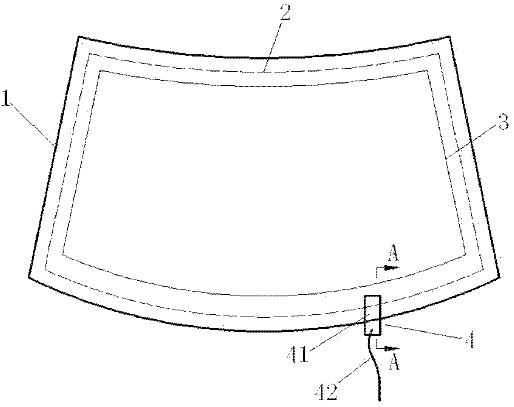
[0033] Schematic reference figure 1 , take a front-shield laminated glass 1 with a small side of 1090mm, a large side of 1410mm, and a height of 850mm, and use green glass + green glass combination. On the inner surface of the outer glass 11, the two hypotenuse edge areas of the glass are printed with a width of 30 mm and the two parallel edge areas of the glass are printed with a black ink printing edge 3 with a width of 50 mm, and the inner glass 12 faces the PVB film. The glass surface of sheet 5 is evenly coated with a single silver low-emissivity coating 2 with a light transmittance greater than 70%. The surface resistance of the film surface is 7.9-8.3Ω / □. High reflectivity, with good thermal insulation properties. The contour of the conductive coating 2 is 20 mm away from the edge of the glass, so the contour of the conductive coating 2 is outside the ink border 3 , and the contour of the black ink border 3 blocks the contour of the conductive coating 2 . The antenna ...

Embodiment 2

[0045] Schematic reference Figure 4 , Take the front windshield laminated glass 1 with a small side of 1090mm, a large side of 1410mm, and a height of 850mm, and use white glass + white glass combination. On the inner surface of the outer glass 11, the two hypotenuse edge areas of the glass are printed with a width of 30 mm and the two parallel edge areas of the glass are printed with a black ink printing edge 3 with a width of 50 mm, and the inner glass 12 faces the PVB film. The glass surface of sheet 5 is evenly coated with double-silver low-emissivity coating 2 with light transmittance greater than 70%. The surface resistance of the film surface is 2.5-3Ω / □. High reflectivity, with good heat insulation performance. The contour of the conductive coating 2 is 2mm away from the solid edge of the black ink border 3, then the contour of the conductive coating 2 is within the ink border 3 and within the field of vision, and the contour of the black ink border 3 will not block ...

Embodiment 3

[0051] Schematic reference Figure 4 , take a front-shield laminated glass 1 with a small side of 1175mm, a large side of 1445mm, and a height of 925mm, and use a combination of green glass and green glass. The two hypotenuse edge areas of the glass on the inner surface of the outer glass 11 are printed with black ink printing edges 3 with a width of 25 mm and two parallel edge areas of the glass with a width of 150 mm, and the inner glass 12 faces the PVB film. The glass surface of sheet 5 is evenly coated with a single silver low-emissivity coating 2 with a light transmittance greater than 70%. The surface resistance of the film surface is 7.9-8.3Ω / □. High reflectivity, with good thermal insulation properties. The contour of the conductive coating 2 is 2mm away from the solid edge of the black ink border 3, then the contour of the conductive coating 2 is within the ink border 3 and within the field of vision, and the contour of the black ink border 3 will not block the cont...


PUM


Abstract

The invention provides laminated glass with an antenna function, and relates to laminated glass plated with a membrane layer. The laminated glass comprises two pieces of glass, a polyvinyl butyral (PVB) membrane sandwiched between the two pieces of glass, a conductive plating layer which is plated on a glass surface on which the glass is contacted with the PVB membrane and an antenna joint, wherein the antenna joint comprises a metal sheet and an outgoing cable; and the rear end of the metal sheet is fixedly connected with the outgoing cable. The laminated glass is characterized in that: the metal sheet of the antenna joint is used for integrally cladding an insulating layer; one part at the front end of the antenna joint is positioned between the PVB membrane and the conductive plating layer; and the antenna joint is arranged in a corner L-shaped area at the periphery of the laminated glass. The laminated glass has the advantages that: the antenna function is increased on the basis of the existing laminated glass with a membrane plating function, so that the cost is greatly saved; the antenna joint is coupled with the conductive plating layer through the insulating layer, so thatthe distance between the antenna joint and the conductive plating layer is only the thickness of an insulating layer membrane, a superposed part can be manufactured to the minimum extent, a good capacitive coupling effect can be achieved, and a signal can be more stably received; and the sheet is extremely thin, so that a technical process is easy to control in the production process, and bubblesare difficult to generate.

Description

【Technical field】 [0001] The invention relates to a laminated glass coated with a film layer, in particular to an automobile front windshield using a transparent conductive film as an antenna main body. 【Background technique】 [0002] In the past, car antennas were mostly rod-shaped or whip-shaped antennas protruding from the car body, but now they have gradually developed to integrate the antenna into the vehicle structure, such as the common antennas that are fixedly installed or printed on the rear windshield of the car. The actual situation is that the antenna located at the position of the laminated glass of the front windshield is better at receiving broadcast signals than the antenna at other positions. However, the installation of laminated glass or printed antennas on the front windshield is prohibited due to the impact on the driver's line of sight. In order to avoid this problem, the antenna function of laminated glass has been developed by using conductive coati...

Claims


Application Information

Patent Timeline
Patent Type & Authority Applications(China)
IPC IPC(8): B60J1/02B60R11/00H01Q1/22H01Q1/38
CPCH01Q1/1271
Inventor 张丹群潘成伟林勇熊燕邱柯芳游代波
Owner FUYAO GLASS IND GROUP CO LTD
Why Eureka
Try Eureka