


Quick Research
Generate reliable direction feasibility study reports for your R&D in just a few steps.

Technical Q&A
Discover and master advanced knowledge NOW. Basics, ideas, possibilities, all at once.

Find Solutions
As an expert in R&D theories, this can generate solutions to your technical problems instantly.

Evaluate Feasibility
Analyze your overall solution with one click, know your potential R&D risks in advance.

Monitor Landscape
Get weekly tech updates, stay abreast of the latest tech innovations and key insights.
Method and terminal for realizing video conference cascade
A video conferencing and conference technology, which is applied in the direction of video conferencing system, TV, pulse modulation TV signal transmission, etc. It can solve the problems of poor signal quality, complicated wiring, and many connecting lines.
- Summary
- Abstract
- Description
- Claims
- Application Information
AI Technical Summary
Problems solved by technology
Method used
Image


Examples
Embodiment 1
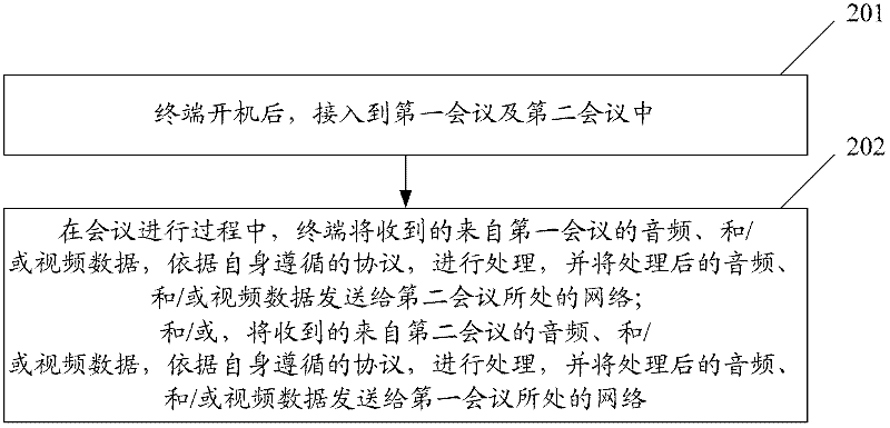
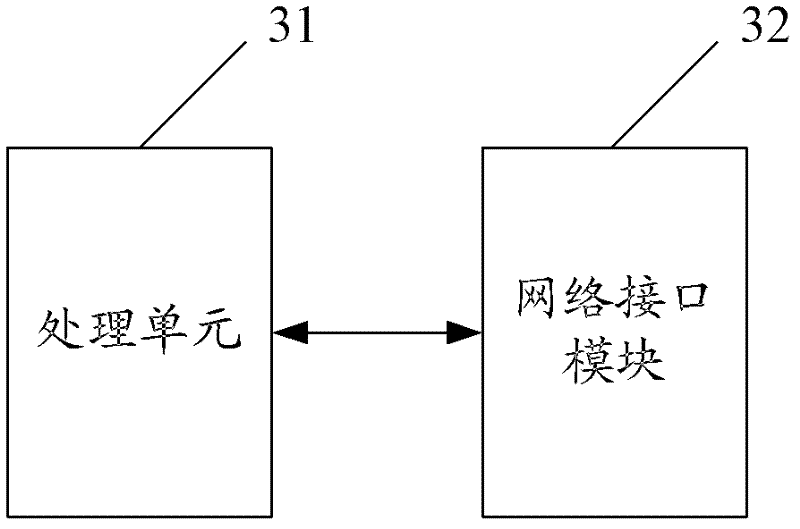
[0211] This embodiment realizes the video conferencing cascade terminal, such as Figure 4 As shown, audio input module, audio encoding module, video input module, video encoding module, network interface module, data multiplexing / demultiplexing module, audio decoding module, video decoding module, audio output module, video output module, signaling processing module, and control and management module; wherein,
[0212] The audio input module is used to digitally collect and process the input audio signal;
[0213] Here, the audio input module supports more than one interface of external devices, for example: supports the input of a microphone, a mixer, and the like.
[0214] The audio encoding module is used to encode the audio data collected and processed digitally and other audio data that needs to be sent;
[0215] Here, in order to reduce the network transmission bandwidth, the terminal generally compresses and encodes the audio and video data. The encoded data is sent...
Embodiment 2
[0245] Figure 11 A schematic diagram of the terminal structure for implementing video conferencing cascading in Embodiment 2, as shown in Figure 11 As shown, the difference between this embodiment and Embodiment 1 is that this embodiment consists of a pair of independent equipment units with similar functions, that is, it is composed of equipment unit 1 and equipment unit 2, and each equipment unit has complete terminal features. In other words, each device unit has the functions of the terminal in Embodiment 1, and each device unit is responsible for accessing a conference. Specifically, equipment unit 1 is responsible for accessing the first conference, and equipment unit 2 is responsible for accessing the second conference. There is mutual connection between the two equipment units. The two equipment units cooperate with each other to realize the exchange of audio and video of the two conferences. data. In order to improve audio and video quality, an IP connection is us...
PUM
 Abstract
Description
Claims
Application Information
 - R&D Engineer
- R&D Manager
- IP Professional
- Industry Leading Data Capabilities
- Powerful AI technology
- Patent DNA Extraction
Browse by: Latest US Patents, China's latest patents, Technical Efficacy Thesaurus, Application Domain, Technology Topic, Popular Technical Reports.
© 2024 PatSnap. All rights reserved.Legal|Privacy policy|Modern Slavery Act Transparency Statement|Sitemap|About US| Contact US: help@patsnap.com