Shell of speed-measuring generator

A technology for tachogenerators and shells, which is applied in the direction of casings/covers/supports, electrical components, electromechanical devices, etc., which can solve the problems of increasing die-casting processes, high prices of aluminum alloy materials, and labor-intensive problems, and achieve the effect of improving work efficiency

Inactive Publication Date: 2012-04-04
钱华
View PDF0 Cites 1 Cited by
  • Summary
  • Abstract
  • Description
  • Claims
  • Application Information

AI Technical Summary

Problems solved by technology

The casing of the prior art is made of die-cast aluminum alloy. In order to securely fix the stator in the casing, the stator and the casing are usually die-cast together. There is a joint at one end of the casing. The outer circle should be coaxial with the inner circle of the stator. The die-casting fixation cannot guarantee the coaxiality between them, so after the stator and the shell are die-casted, the outer circle of the joint part and the inner circle of the stator are generally gold-processed to meet the coaxial requirements.
The deficiencies in the shell are: 1. A die-casting process needs to be added to fix the stator; 2. It is labor-intensive and time-consuming to process the shell and stator; 3. The price of aluminum alloy materials is relatively high; higher cost

Method used


Image

  • Shell of speed-measuring generator
  • Shell of speed-measuring generator
  • Shell of speed-measuring generator

Examples


Embodiment Construction

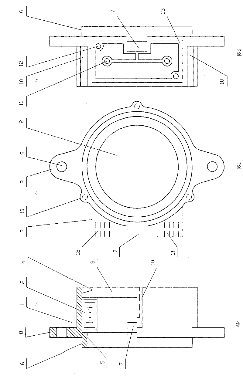
[0016] The outer surface of the left end of the housing 1 is a circular joint 6, the outer circle of the joint 6 is coaxial with the inner circle of the cavity 3; the right side of the joint 6 has a protruding part 8 protruding outward in the radial direction, close to the edge of the protruding part There is a hole 9 at the place, and the test generator is fixed at the coaxial position corresponding to the speed-measuring part with the joint 6 as the reference through connecting pieces such as bolts. The protruding part 8 can be a flange, or a plurality of semi-elliptical or trapezoidal symmetrically arranged parts to reduce material consumption. The protruding part 8 in this embodiment is two symmetrically arranged trapezoidal parts .

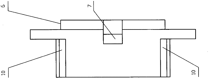
[0017] The left end of the casing 1 is provided with an outlet 7 for the lead wires of the stator winding to protrude. The shape of the outlet 7 on the surface of the casing can be U-shaped or a rectangle with one side missing.

[0018] A pl...


PUM


Abstract

This invention discloses a shell (1) of a speed-measuring generator, wherein the shell (1) is cylinder-shaped in general; the interior of the shell (1) is provide with a cavity body (3) portion capable of containing a stator (2); the left end of the cavity body (3) is provided with a bump part (5) portion capable of limiting the stator (2); the outer surface of the left end of the shell (1) is a circular joint (6); the right side of the joint (6) is provided with a protruding part (8) which is extended outwardly along a radial direction; holes (9) are arranged closely the edge of the protruding part; an outgoing line outlet (7) is formed on the left end of the shell (1), wherein a stator winding lead is extended out of the outgoing line outlet (7); the wall of one side of the outgoing line outlet (7) on the shell (1) is also provided with a line connection board box (13); the shell (1) disclosed by this invention is characterize in that the shell (1) is made of phenolic aldehyde plastic in an integrated-plastic method; the stator (2) can be pressed into the right end of the cavity body (3) and is retained in the cavity body (3); compared with the prior art, metal processing procedures of the shell and the stator can be saved; the consumption material of the shell is little; and the shell (1) disclosed by this invention has benefit technology effects of saving energy, reducing consumption and increasing working efficiency.

Description

technical field [0001] The present invention relates to a casing, in particular to a casing for a tachogenerator. The casing of the tachogenerator is generally cylindrical. There is a cavity in the casing which can accommodate a stator. A pair of stators are arranged at the left end of the cavity. For the protrusion part of the limit function, the outer surface of the left end of the shell is a circular joint, and the right side of the joint has a protrusion protruding outward in the radial direction, and a hole is provided near the edge of the protrusion, and the left end of the shell has a Outlet for the stator winding leads to protrude from. Background technique [0002] In the case of motor speed regulation, a tachometer generator is generally used to detect its speed. The tachogenerator is composed of a stator, a rotor, and a casing, and the casing is generally cylindrical. The casing of the prior art is made of die-casting aluminum alloy. In order to securely fix the...

Claims


Application Information

Patent Timeline
IPC IPC(8): H02K5/02H02K5/04H02K5/22
Inventor 秦存鸿
Owner 钱华
Why Eureka
Try Eureka