Optical fiber butt joint device
A docking device and optical fiber technology, applied in the field of optical fiber connection devices, can solve the problems of not allowing the space for remaining optical fibers to be coiled, changing the optical transmission characteristics of optical fibers, increasing the loss of optical fiber joints, etc., achieving simple structure, good long-term stability, and reducing The effect of testing time and cost
- Summary
- Abstract
- Description
- Claims
- Application Information
AI Technical Summary
Problems solved by technology
Method used
Image
Examples
Embodiment 1
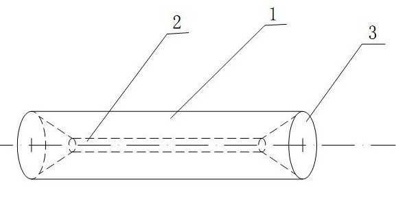
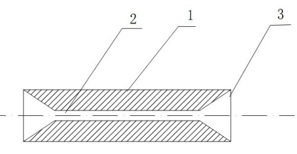
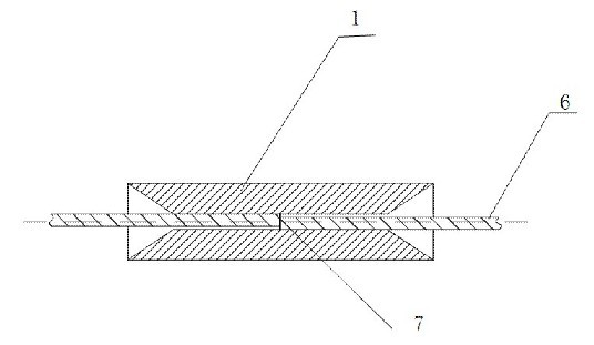
[0049] Such as figure 1 , figure 2 , image 3 with Figure 4 As shown, there are tapered inlet holes 3 at both ends of the tubular structure 1 made of memory alloy, and the inner hole 2 is located between the two tapered inlet holes 3 and they are connected. The initial inner diameter of the inner hole 2 is D T1 , Inner diameter D after low temperature expansion T2 The relationship with fiber 6 is:
[0050] [ 1 - (1-S) × K ] × D F T1 F (3)
[0051] D. F T2 F × ( 1+ S×K ) (4)
[0052] D. F It is the outer diameter of the optical fiber 6 at the time of docking. It often refers to the bare optical fiber with the coating removed. The outer diameter of the bare optical fiber for communication is 125 microns, and the positive and negative deviation is not more than 0.7 microns. K is the shape of the tubular structure 1 composed of memory alloy materials. The memory gauge coefficient, S is the selected proportional coefficient, and the generally preferr...
Embodiment 2
[0058] Such as Figure 5 As shown, in this embodiment, the difference from Embodiment 1 is that the optical fiber inlets at both ends of the tubular structure 1 are trumpet-shaped inlets 4 . This structure can reduce the volume of the tubular structure 1 and increase the diameter of the introduction port, so as to facilitate the introduction and docking of the optical fiber 6 . In this embodiment, the structures, connections and working principles of other parts are the same as those in Embodiment 1.
[0059]
Embodiment 3
[0061] Such as Image 6 , Figure 7 , Figure 8 As shown, in this embodiment, the A connector 10 has a guide rod 8 and includes the ends of four optical fibers 6, wherein the ends of the four optical fibers are located in the middle of the array tubular structure 9, and the array tubular structure 9 is composed of the substrate 12 and the The function board 13 is formed by riveting, welding or adhesive bonding. The function board 13 is made of a flat plate made of memory alloy material by low-temperature stamping or rolling. The diameter of the inscribed circle of the cavity satisfies formula (4), and the diameter of the inscribed circle of the shrunk cavity satisfies formula (3); there are guide holes 11 and the ends of four optical fibers 6 in the B connector 15, and the A connector 10 is inserted into the B connector 15, and the guide rod 8 is slidably fitted and positioned with the guide hole 9, so that the ends of the optical fibers 6 contained in the B connector 15 and...
PUM
| Property | Measurement | Unit |
|---|---|---|
| Thickness | aaaaa | aaaaa |
Abstract
Description
Claims
Application Information
 - R&D Engineer
- R&D Manager
- IP Professional
- Industry Leading Data Capabilities
- Powerful AI technology
- Patent DNA Extraction
Browse by: Latest US Patents, China's latest patents, Technical Efficacy Thesaurus, Application Domain, Technology Topic, Popular Technical Reports.
© 2024 PatSnap. All rights reserved.Legal|Privacy policy|Modern Slavery Act Transparency Statement|Sitemap|About US| Contact US: help@patsnap.com


