Carburetor

A carburetor and float technology, which is applied in the field of atomization devices, can solve the problems of reducing the pressure drop of the main nozzle, inconvenient processing, and the influence of oil level height, and achieve the effects of reducing production costs, good sealing effect, and improving reliability.

Inactive Publication Date: 2012-03-28
成都恒高机械电子有限公司
View PDF7 Cites 2 Cited by
  • Summary
  • Abstract
  • Description
  • Claims
  • Application Information

AI Technical Summary

Problems solved by technology

[0003] Existing plunger carburetors generally do not have an accelerator pump device, and cannot provide additional acceleration fuel to the engine when the motorcycle speeds up; some have an accelerator pump device, but the accelerator nozzle of the accelerator pump device is located closer to the main nozzle. Throat air inlet, so the existence of the accelerating nozzle will reduce the pressure drop of the main nozzle, thereby reducing the fuel injection quantity of the main nozzle, and cannot achieve the best acceleration effect
[0004] And when the screw plug is installed on the existing carburetor, the threaded through hole is directly opened on the outer wall of the carburetor, and then the screw plug is installed in the through hole. This method makes the carburetor seal strength low and the sealing The effect is not good, and it also affects the strength of the outer wall of the carburetor
[0005] The floats of the existing carburetors are all of one-piece structure, and the use of one-piece structure will cause the swing of the carburetor float to be restricted, thereby affecting the height of the oil level
[0006] The connecting pipe connected to the float needle valve assembly of the existing carburetor is an elbow, which is easy to age after a long time of use, resulting in oil leakage, and the processing is inconvenient and costly

Method used


Image

  • Carburetor
  • Carburetor
  • Carburetor

Examples


Embodiment Construction

[0029] The present invention will be further described below in conjunction with accompanying drawing:

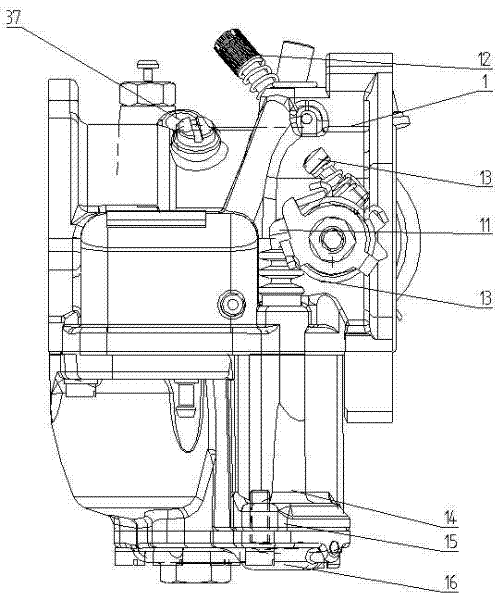
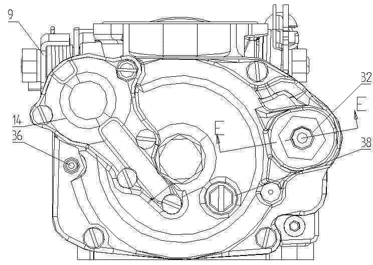
[0030] like Figure 1 to Figure 4 , Figure 8 As shown, a carburetor includes a carburetor body 1 and a float cover 2, a float chamber is arranged between the carburetor body 1 and the float cover 2, a throat is arranged in the carburetor body 1, and the carburetor The throttle shaft 3 is installed in the carburetor body 1, and the throttle valve 4 installed on the throttle shaft 3 is located in the throat pipe. Valve suspension assembly 5, a return spring 6 is provided between the throttle suspension assembly 5 and the carburetor body 1, and the throttle cable is connected to the throttle suspension assembly 5; the other end of the throttle shaft 3 passes through the throttle shaft sleeve 7 Installed on the main body of the carburetor, the part of the throttle shaft sleeve 7 beyond the carburetor is provided with a bracket assembly 8, the end of the throttle shaft 3 is p...


PUM


Abstract

The invention discloses a carburetor which comprises a carburetor body (1) and a float cover (2), wherein the float cover (2) is connected with an accelerating pump (14), a diaphragm (18) of a cavity (17) is arranged at the end part of a top bar (19), and the top bar (19) is pressed against a mast base assembly (8); the cavity (17) is communicated with a float chamber by an accelerating oil duct (24), a pump body (15) is provided with an accelerating nozzle (26), and the accelerating nozzle (26) is arranged behind a main nozzle (42); a float (28) is provided with a gap, and a straight tube (32) communicated with a needle valve seat is arranged on the float cover (2). The carburetor disclosed by the invention has the advantages that: the accelerating nozzle (26) is arranged behind the main nozzle (42), so that the operation of the accelerating pump (14) can not cause reduction of the fuel injection amount of the main nozzle (42), therefore, the accelerating effect is good; and the outsides of through holes (for installing plugs) of the carburetor body (1) and the float cover (2) are respectively provided with a boss, therefore, the sealing effect is good.

Description

technical field [0001] The invention relates to an atomizing device in a fuel supply system of a fuel engine, in particular to a carburetor. Background technique [0002] The function of the carburetor is to introduce outside air into the carburetor and mix it with fuel to form oil and gas, and then input it into the engine to use the ignition device to ignite and explode, and the piston that can push the cylinder generates power to drive the drive wheel to rotate to achieve the goal of moving forward. Purpose, its working process is: the fuel in the float chamber of the carburetor enters the throat through the main metering hole and the nozzle, mixes with the high-speed airflow in the throat, and atomizes into the gasoline engine; its working principle is: when the gasoline engine generates negative pressure, it attracts When the high-speed airflow passes through the throat, when the pressure of the main nozzle is lower than the pressure of the float chamber, the fuel will ...

Claims


Application Information

Patent Timeline
Patent Type & Authority Applications(China)
IPC IPC(8): F02M7/12
Inventor 范国平唐建斌汪澜陈永秋杨平王朕
Owner 成都恒高机械电子有限公司
Why Eureka
Try Eureka