
Protective plate-free steel band water-cooling quenching device

A quenching device and water cooling technology, which is applied in the direction of quenching device, heat treatment equipment, furnace, etc., can solve the problems of increasing the cost of steel strip quenching, troublesome operation of workers, and reducing the thermal conductivity of the pressing plate, so as to improve the surface quality and hardenability , The effect of reducing the scrap rate

Inactive Publication Date: 2012-03-28
ZHEJIANG BAINAI STEEL STRIP
View PDF5 Cites 9 Cited by
  • Summary
  • Abstract
  • Description
  • Claims
  • Application Information

AI Technical Summary

Problems solved by technology

But it has four disadvantages: one is to use a protective plate, which is used to protect the pressure plate and the steel strip so that it will not be strained during the quenching process, which increases the cost of quenching the steel strip; two. The expanded graphite used as the protective plate is relatively soft. If the steel strip is uneven or has burrs or the dust in the heating furnace is brought out, there will be strips of grooves on the protective plate, leaving many grooves on the surface of the steel strip. Graphite stripes, many stripes are formed on the surface of the steel strip after tempering, which affects the surface quality of the steel strip; third, because the service life of the protection plate is not long, it needs to be replaced frequently, which makes it troublesome for workers to operate, and every time the protection plate is replaced, it will be scrapped The steel strip of more than one meter increases the scrap rate of the steel strip heat treatment; the fourth is that the heat conduction capacity of the pressing plate is reduced after the protective plate is used, so the equipment cannot harden the thicker steel strip

Method used


Image

  • Protective plate-free steel band water-cooling quenching device
  • Protective plate-free steel band water-cooling quenching device
  • Protective plate-free steel band water-cooling quenching device

Examples


Embodiment Construction

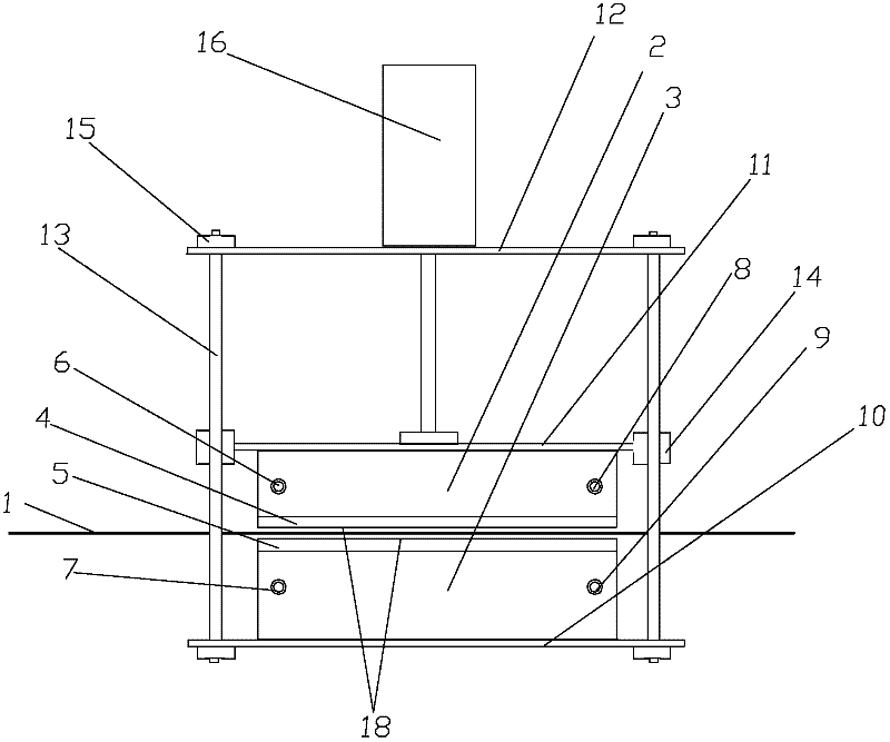
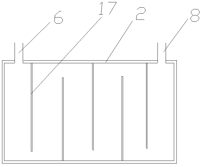
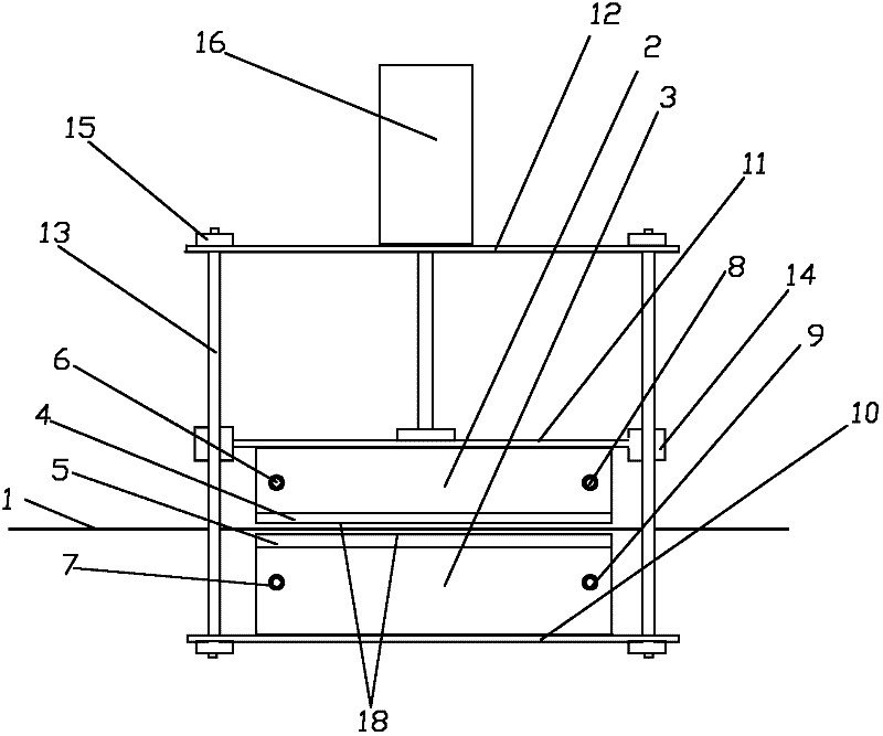
[0016] Such as figure 1 and figure 2 As shown, a steel strip water cooling and quenching device without a protective plate includes an upper fixed plate 12, a lower fixed plate 10, a column 13 fixed between the upper fixed plate 12 and the lower fixed plate 10, and the upper fixed plate 12 An upper water tank 2 is arranged on the top, an upper pressing plate 4 is provided at the bottom of the upper water tank 2, a lower water tank 3 is arranged on the lower fixing plate 10, and a lower pressing plate 5 is arranged on the top of the lower water tank 3, and the upper pressing plate 4 and A steel strip 1 that is cooled and quenched through the heat conduction of the upper press plate 4 and the lower press plate 5 is passed between the lower press plates 5 , and the surfaces of the upper press plate 4 and the lower press plate 5 are both electroplated with a hard chromium layer 18 . The material of the upper pressing plate 4 and the lower pressing plate 5 is 65Mn steel plate que...


PUM


Abstract

The invention provides a protective plate-free steel band water-cooling quenching device which comprises an upper fixed plate, a lower fixed plate and a stand column fixed between the upper and lower fixed plates; an upper water tank is arranged on the upper fixed plate; an upper pressing plate is arranged at the bottom of the upper water tank; a lower water tank is arranged on the lower fixed plate; a lower pressing plate is arranged at the top of the lower water tank; a steel band which is used for cooling quenching through the heat conduction of the upper and lower pressing plates is penetrated between the upper and lower pressing plates; and hard chromium layers are electroplated on the surfaces of both the upper and lower pressing plates. Through the invention, the cost of the heat treatment of the steel band is decreased, the stripes on the surface of the steel band are decreased, the surface quality of the steel band is improved, the rejection ratio of the heat treatment of the steel band is decreased and the quenching degree of the steel band is improved.

Description

technical field [0001] The invention relates to the field of steel strip heat treatment, in particular to a steel strip water cooling and quenching device without a protective plate. Background technique [0002] Steel strip quenching generally uses oil-sprayed pressure plate equipment, which is a product of the 1960s. When oil is sprayed on the hot steel strip, a large amount of smoke will be generated, making the whole workshop smoky, and the workshop is full of oil pollution. Serious polluted environment. The invention patent with the patent number of 200810063322.5 provides a water-cooled platen quenching device for steel strips. This device uses water to cool the platen by passing water into the water tank, and then uses the principle of solid heat conduction to cool the steel strip with the platen. The steel strip does not Contact with water will not produce smoke, so it will not pollute the environment. Compared with the oil-injected pressure plate, it not only has ...

Claims


Application Information

Patent Timeline
IPC IPC(8): C21D1/673C21D9/52
Inventor 李益明林名钟
Owner ZHEJIANG BAINAI STEEL STRIP
Learn More