
Impeller type vacuum quantitative packaging machine

A quantitative packaging, impeller-type technology, applied in the direction of packaging, packaging, transportation and packaging under vacuum/special atmosphere, can solve the problems of unsatisfactory packaging reliability and accuracy, interruption of filling operations, insufficient filling of packaging bags, etc.

Active Publication Date: 2012-03-28
秦皇岛普达电子有限公司
View PDF4 Cites 10 Cited by
  • Summary
  • Abstract
  • Description
  • Claims
  • Application Information

AI Technical Summary

Problems solved by technology

[0002] With the increasing demand for large-scale packaging, automatic packaging machines of various specifications and models have appeared on the market. Common automatic packaging machines can automatically fill materials into packaging bags, but they are easily trapped in the materials during the filling process. Doped with air, resulting in fluffy materials, insufficient filling of packaging bags, and unsatisfactory packaging reliability and precision
At present, there are vacuum packaging machines on the market. The material filling process is carried out in the vacuum chamber. The air in the packaging bag and the air mixed with the material can be sucked away by the vacuum fan. This type of vacuum packaging machine has a fast filling speed and the material is compressed. , the filling rate has been effectively improved, but the material in the silo is very easy to accumulate and block the discharge pipe due to the negative pressure of the vacuum silo, resulting in frequent interruption of the filling operation, and a large amount of dust generated during packaging, which deteriorates the production environment. Therefore, there is an urgent need for a packaging machine with a high degree of automation, smooth operation process, effective dust suppression, and ideal packaging accuracy.

Method used


Image

  • Impeller type vacuum quantitative packaging machine
  • Impeller type vacuum quantitative packaging machine
  • Impeller type vacuum quantitative packaging machine

Examples


Embodiment Construction

[0020] The present invention will be described in further detail below in conjunction with the accompanying drawings.

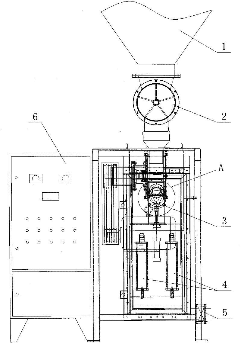
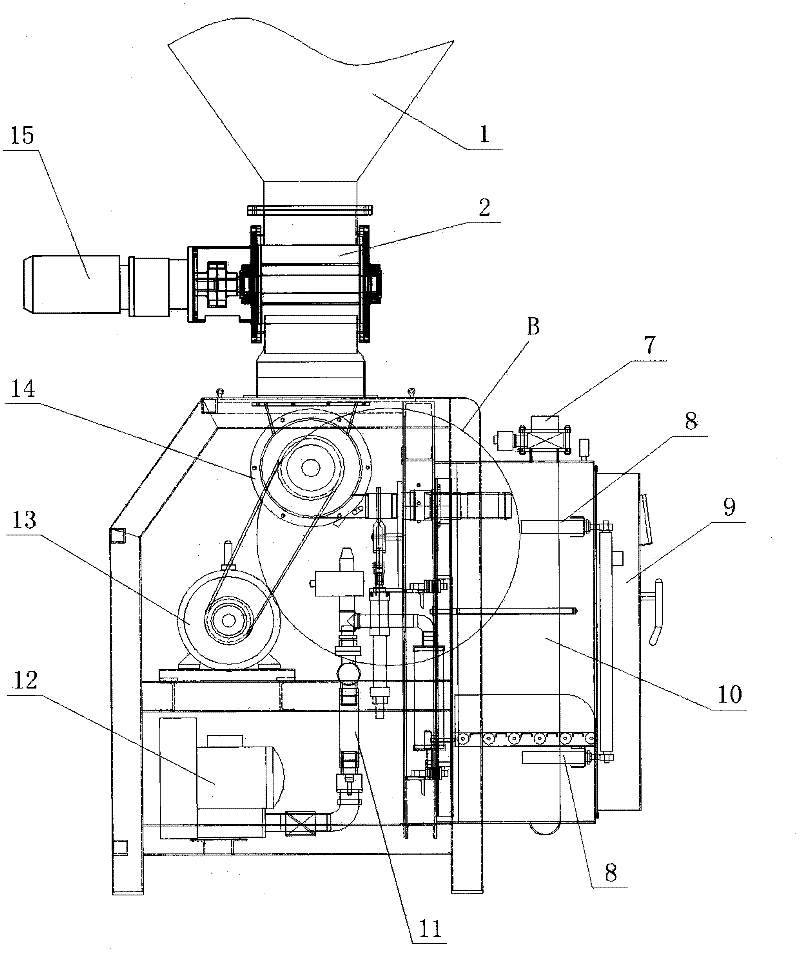
[0021] Such as figure 1 , image 3 As shown, an impeller type vacuum quantitative packaging machine of the present invention is provided with a star-shaped feeder 2 at the lower part of the feed bin 1, an impeller bin 14 is arranged at the lower part of the star-shaped feeder 2, and an impeller is arranged in the impeller bin 14. ; A vacuum chamber 10 is provided on the front side of the packaging machine frame.

[0022] Preferably, the impeller can be a vertical impeller or a horizontal impeller, the blades are fixed on the driving wheel by bolts, and the blades can be replaced.

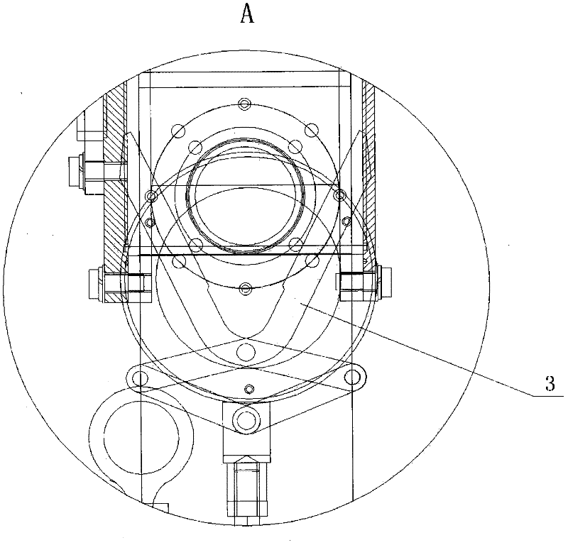
[0023] Such as figure 1 , image 3 , Figure 4 As shown, further, the bottom of the impeller chamber 14 is provided with a discharge port, the discharge port is connected to the buffer pipe of the vacuum chamber 10, and a scissor valve 3 is arranged at the discharge port, betw...


PUM


Abstract

The invention discloses an impeller type vacuum quantitative packaging machine. The packaging machine is characterized in that a packing driving mechanism of the packaging machine comprises an impeller, and the material driving speed of the impeller is obviously better than the material driving speed of a packing auger, thereby being capable of greatly accelerating the material packing speed of the packaging machine; the material sealing effect of the impeller is good, and a discharge port can be effectively blocked after the end of packaging, thereby preventing the leakage of material; the packaging machine is simultaneously provided with a control valve of scissors at the discharge port, and the control valve of the scissors can flexibly control the discharge flow rate and ensure the requirements on packaging precision; the packaging machine is provided with a bag expansion device at a discharge nozzle, thereby preventing dust from flying to outside during packaging; and an impellerdriving electric motor of the packaging machine can be controlled by a programmable logic controller (PLC) and a frequency converter, thereby having the characteristics of being intelligent and automatic.

Description

technical field [0001] The invention relates to a quantitative packaging machine used in packaging processing operations, in particular to a packaging material machinery. Background technique [0002] With the increasing demand for large-scale packaging, automatic packaging machines of various specifications and models have appeared on the market. Common automatic packaging machines can automatically fill materials into packaging bags, but they are easily trapped in the materials during the filling process. Doped with air, resulting in fluffy materials, insufficient filling of packaging bags, and unsatisfactory packaging reliability and precision. At present, there are vacuum packaging machines on the market. The material filling process is carried out in the vacuum chamber. The air in the packaging bag and the air mixed with the material can be sucked away by the vacuum fan. This type of vacuum packaging machine has a fast filling speed and the material is compressed. , th...

Claims


Application Information

Patent Timeline
IPC IPC(8): B65B1/10B65B1/30B65B1/32B65B31/02
Inventor 陈洁陈林陈浩
Owner 秦皇岛普达电子有限公司
Learn More