
Convenient medical positive-pressure remaining needle

A convenient technology for indwelling needles, applied in the direction of needles and instruments introduced into the body, it can solve the problems of unguaranteed positive pressure effect, danger, blood clot blocking the pipeline, etc., and achieve good tube sealing effect, good indwelling effect, and good safety Effect

Inactive Publication Date: 2014-01-01
张丽君
View PDF5 Cites 3 Cited by
  • Summary
  • Abstract
  • Description
  • Claims
  • Application Information

AI Technical Summary

Problems solved by technology

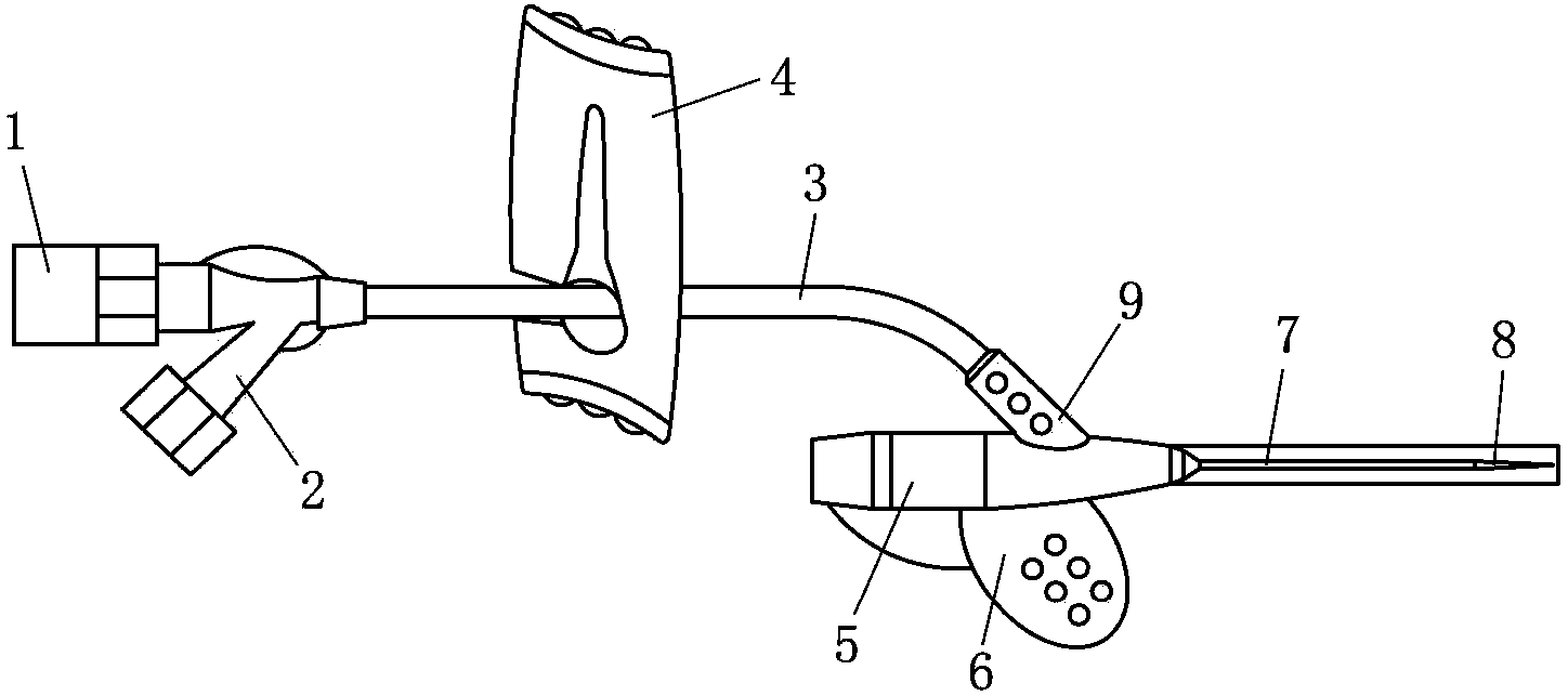
[0004] However, for figure 1 As far as the medical indwelling needle is concerned, since the water-stop clamp 4 needs to squeeze the extension tube with your fingers until the thin end of the water-stop clamp is clamped when sealing the tube, a negative pressure will be formed in the lumen after letting go, which will easily cause blood to flow back into the tube. Catheters, clots form to block the tubes and cannot be reused, and even when the indwelling needle is reused, the clots can be injected into the patient's vein, causing danger
In addition, since the water stop clamp 4 must push the extension tube with both hands in accordance with the method of "pushing while retreating, pulling out the needle with fluid", "hands upside down, fingertips pressurized", if a good positive pressure is required The tube sealing effect must be implemented strictly in accordance with the requirements, the operation is cumbersome, and a good positive pressure effect cannot be guaranteed, and the fineness of the operation is required to be high

Method used


Image

  • Convenient medical positive-pressure remaining needle
  • Convenient medical positive-pressure remaining needle
  • Convenient medical positive-pressure remaining needle

Examples


Embodiment Construction

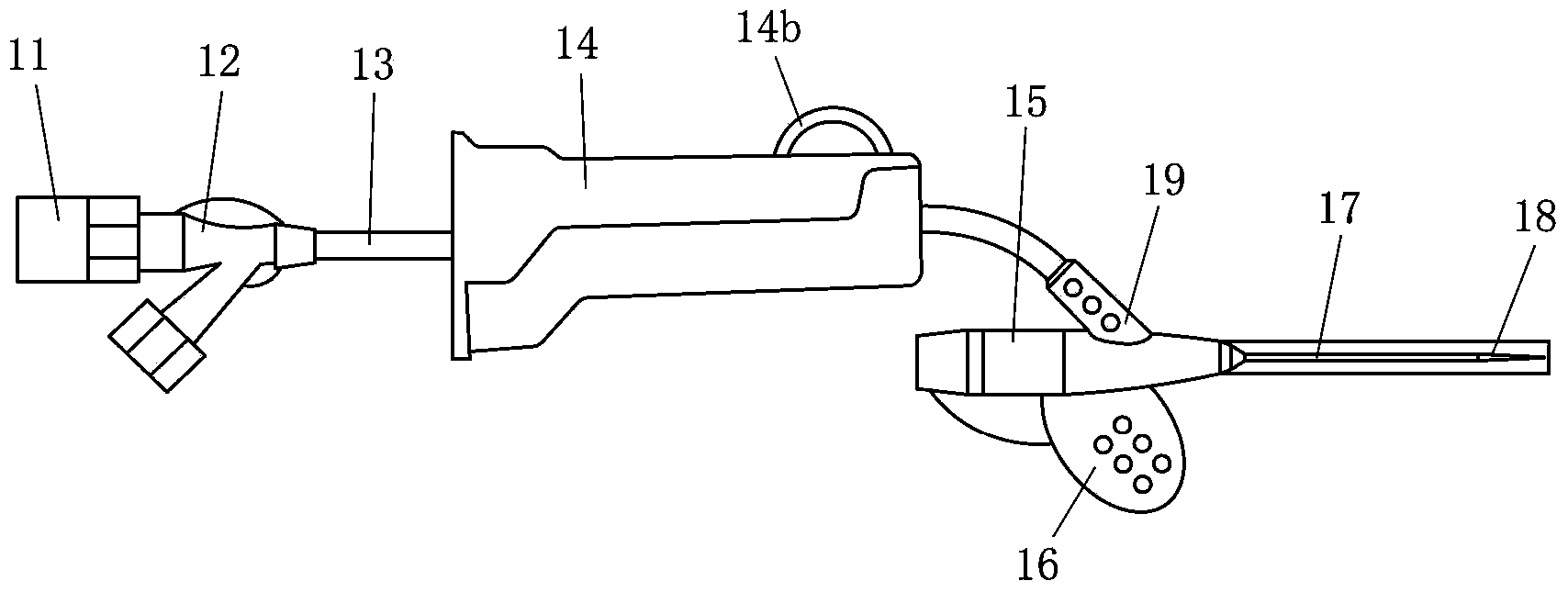
[0023] Hereinafter, an exemplary embodiment of the medical convenient positive pressure indwelling needle of the present invention will be described in detail with reference to the accompanying drawings.

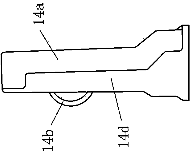
[0024] figure 2 A schematic structural view of an exemplary embodiment of the medical convenient positive pressure indwelling needle according to the present invention is shown. Figure 3A show figure 2 Schematic side view of the water stop in . Figure 3B show figure 2 A schematic top view of the water stop in . Figure 3C show figure 2 A schematic diagram of one end of the water stop (also known as the front end or small end of the water stop body). Figure 3D show figure 2 A schematic diagram of the other end of the water stop (also known as the rear end or the big end of the water stop body).

[0025] Such as figure 2 As shown, in an exemplary embodiment of the present invention, the medical convenient positive pressure indwelling needle includes a heparin ...


PUM


Abstract

The invention provides a convenient medical positive-pressure remaining needle which comprises a puncture needle, a catheter, an extension tube, an infusion tube line and a water stop. The water stop comprises a water stop body, an extension-tube passage, a wheel shaft groove and a toothed pulley, the extension-tube passage is arranged in the water stop body and used for accommodating one section of the extension tube, a plurality of protruding teeth arranged on the circumferential surface of the toothed pulley and a wheel shaft extending along an axis of the protruding teeth are arranged on the toothed pulley, the wheel shaft groove is arranged in the water stop body along the length direction of the extension-tube passage, and the wheel shaft of the toothed pulley is mounted in the wheel shaft groove and can move along the wheel shaft groove back and forth. The water stop is structurally characterized in that with forward movement of the wheel shaft of the toothed pulley in the wheel shaft groove, the distance between the wheel shaft of the toothed pulley and the extension tube in the extension-tube passage gets shorter, till the protruding teeth of the toothed pulley are completely pressed against a section of the extension tube located in the extension-tube passage. The convenient medical positive-pressure remaining needle has the advantages of good tube-sealing effect, convenience and rapidness in operation, good remaining effect, good security and the like.

Description

technical field [0001] The invention relates to the technical field of medical indwelling needles, in particular to a medical positive pressure indwelling needle with convenient operation. Background technique [0002] At present, medical indwelling needles (also known as venous indwelling needles or venous trocars) are commonly used equipment for infusion therapy. The core components of conventional medical indwelling needles include soft catheters that can be indwelled in blood vessels, and stainless steel puncture guide cores. When in use, the catheter and the needle core are punctured into the blood vessel together. After the catheter has completely entered the blood vessel, the needle core is withdrawn, and only the soft catheter is left in the blood vessel for infusion therapy. [0003] For example, figure 1 A schematic structural view of a medical indwelling needle commonly used in the prior art is shown. Such as figure 1 As shown, a typical medical indwelling nee...

Claims


Application Information

Patent Timeline
IPC IPC(8): A61M5/158
Inventor 张丽君陈细瑜
Owner 张丽君
Learn More