Motor speed adjusting device

A motor speed controller and capacitor technology, which is applied in the direction of excitation or armature current control, etc., can solve the problems of high cost, inability to realize stepless speed regulation, high-frequency interference, etc., and achieve low production cost, simple circuit, and easy implementation Effect

Active Publication Date: 2012-03-21
GREE ELECTRIC APPLIANCES ZHONGSHAN SMALL HOUSEHOLD APPLIANCES MFG +1
View PDF5 Cites 4 Cited by
  • Summary
  • Abstract
  • Description
  • Claims
  • Application Information

AI Technical Summary

Problems solved by technology

[0008] Aiming at the deficiencies of the above prior art, the purpose of the present invention is to provide a cheap, simple and feasible variable reactance stepless speed regulation scheme on the premise of avoiding high-frequency interference, so as to solve the problem that the existing motor speed regulation cannot The problem of realizing stepless speed regulation, generating high-frequency interference, and being expensive makes it impossible to popularize

Method used


Image

  • Motor speed adjusting device
  • Motor speed adjusting device
  • Motor speed adjusting device

Examples


Embodiment Construction

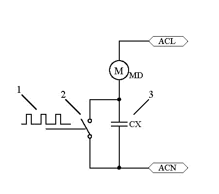
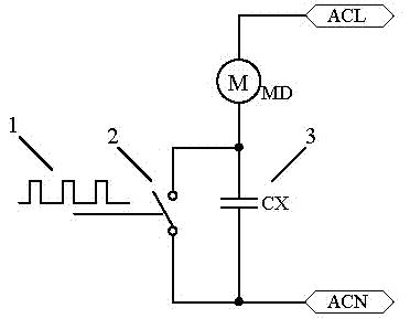
[0019] Such as figure 1 and figure 2 As shown, the PWM unit of the present invention is mainly composed of a pulse wave generation chip U1 and a variable resistor POT2, and the duty cycle of the pulse wave can be changed when POT2 is adjusted. The main control circuit controls the discharge circuit through the pulse signal. Both ends of CX in the load unit are connected to the filter capacitor C4 through the rectifier bridge stack BD1. The PWM unit outputs a pulse signal, which is added to the control pole of the power tube Q1 through the R3 of the main control circuit to control the power tube to be turned on or off. During the high-level period of the pulse wave, Q1 is turned on, so that the capacitor CX is discharged through the discharge circuit of the main control circuit; during the low-level period of the pulse wave, Q1 is turned off, the discharge circuit is disconnected, the load unit charges CX, and the capacitor is alternately charged The discharge causes the re...


PUM


Abstract

The invention relates to a motor speed adjusting device. A control circuit of the motor speed controller mainly comprises a PWM (pulse-width modulation) unit, a main control unit and a load unit, wherein the PWM unit outputs a pulse wave with an adjustable duty ratio to the main control unit, the main control unit is connected with two ends of a capacitor of the load unit in parallel so as to be used for controlling the capacitor to charge or discharge, the capacitor of the load unit is in serial connection on a motor needing of speed adjustment, the PWM unit outputs the pulse wave to the main control unit, the main control unit taken as a switch is connected at the two ends of the capacitor of the load unit in parallel, the load unit and the capacitor are connected on the motor in series, the pulse wave controls the connection and the disconnection of the switch to carrying out charge and discharge on the capacitor, when the duty ratio of the pulse wave is adjusted, and changed pulse signals are converted into the change of charge and discharge time of the capacitor by the main control unit, so that the reactance value of a reactor can change along with the change of the charge and discharge time, so as to realize stepless speed adjustment. Compared with the prior art, the motor speed adjusting device is easy in circuit, easy to realize, low in manufacturing cost, simultaneously can not generate high-frequency interference and can realize the stepless speed adjustment on the motor.

Description

technical field [0001] The invention relates to a motor system of a household appliance, in particular to a motor governor. Background technique [0002] Currently known motor speed regulation methods are mainly divided into the following four types: [0003] 1. Tap speed regulation is realized by changing the stator winding. This technology is mature, low in cost, and widely used, but it belongs to gear speed regulation and cannot realize stepless speed regulation. [0004] 2. Reactor speed regulation is realized by reducing the applied voltage of the motor, and it is divided into traditional reactor speed regulation and capacitive reactor speed regulation. The former is characterized by easy speed adjustment of each gear, simple winding, and convenient maintenance, but the inductor is large in size, heavy in weight, poor in speed regulation performance, and difficult to start at low speed gears; compared with the former, the latter has improved startup performance and sp...

Claims


Application Information

Patent Timeline
IPC IPC(8): H02P7/30
Inventor 何文培张秋俊唐鋆姣李剑生
Owner GREE ELECTRIC APPLIANCES ZHONGSHAN SMALL HOUSEHOLD APPLIANCES MFG
Why Eureka
Try Eureka