Microstrip line, impedance converter applying microstrip line and design method of microstrip line

A technology of impedance converter and design method, which is applied in the field of microstrip lines, and can solve the problems of affecting the frequency response of the system, increasing the area of ​​circuit layout, and degrading the directivity of communication devices, etc.

Inactive Publication Date: 2012-03-21
SHENZHEN FUTAIHONG PRECISION IND CO LTD +1
View PDF4 Cites 1 Cited by
  • Summary
  • Abstract
  • Description
  • Claims
  • Application Information

AI Technical Summary

Problems solved by technology

QTEM has odd mode (Odd mode) and even mode (Even mode), because the transmission phase speeds of these two modes are generally different during non-linear transmission (odd mode transmission phase speed VO>even mode transmission phase speed VE) , it is easy to cause the directivity of the communication device to deteriorate, thereby affecting the frequency response of the system
In addition, most of the existing microstrip lines are long in length. For example, when used to transmit signals with a center frequency of about 2.5GHz or 5.8GHz, the length of the microstrip line generally needs to reach about 27mm, which easily increases the circuit layout area. , which is not conducive to the miniaturization of communication devices

Method used


Image

  • Microstrip line, impedance converter applying microstrip line and design method of microstrip line
  • Microstrip line, impedance converter applying microstrip line and design method of microstrip line
  • Microstrip line, impedance converter applying microstrip line and design method of microstrip line

Examples


Embodiment Construction

[0033] The invention discloses a microstrip line, which can be applied to circuits that need to use impedance converters.

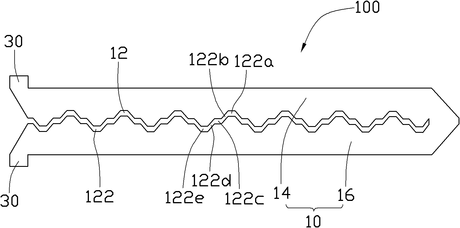
[0034] see figure 1 , the microstrip line 100 is a metal sheet, which is used for impedance matching in the circuit. In this embodiment, the central operating frequencies of the microstrip line 100 are about 2.5 GHz and 5.8 GHz. The microstrip line 100 includes an annular strip 10 and two side strips 30 located in the same plane. The two side strips 30 are symmetrically arranged at opposite ends of the annular strip 10. Electromagnetic wave signals are fed from the one side strip 30 and pass through the loop. The belt 10 is conveyed and finally fed out from the other side belt 30 .

[0035] The annular belt 10 is roughly in the shape of a "U", and a slot 12 is set in the middle thereof, and one end of the slot 12 passes through one end of the annular belt 10, and then the annular belt 10 is divided into a first side belt 14 oppositely arranged. And a s...


PUM


Abstract

The invention provides a microstrip line. The microstrip line is applied in a circuit to play a role in impedance matching and is characterized in that: the microstrip line comprises an annular strip and two side strips, wherein the two side strips are arranged on the two sides of the annular strip and are respectively used for feeding in and feeding out an electromagnetic wave signal; and a groove is formed in the annular strip so as to increase an odd mode transmission route of the microstrip line. The invention also provides an impedance converter applying the microstrip line and a design method of the microstrip line; and the microstrip line designed by the method has good frequency response and greatly reduced size.

Description

technical field [0001] The invention relates to a microstrip line, in particular to a microstrip line used for an impedance converter and a design method thereof. Background technique [0002] With the rapid development of microwave communication technology, more and more places use microstrip lines. Microstrip line is a commonly used waveguide device in the microwave band, which is mostly used for microwave signal transmission, impedance conversion, bandpass filtering, phase shifting or delay line, etc. When the microstrip line is used for microwave propagation, it mainly relies on the quasi-transverse electromagnetic field mode (Quasi-Transverse Electric Magnetic mode, QTEM) between the metal conduction band and the metal plate to realize microwave signal transmission. QTEM has odd mode (Odd mode) and even mode (Even mode), because the transmission phase speeds of these two modes are generally different during non-linear transmission (odd mode transmission phase speed VO&...

Claims


Application Information

Patent Timeline
IPC IPC(8): H01P3/08H01P11/00
Inventor 邱大舜
Owner SHENZHEN FUTAIHONG PRECISION IND CO LTD
Why Eureka
Try Eureka