Vacuum transmission processing equipment and method
A technology of vacuum transmission and process equipment, applied in the direction of final product manufacturing, sustainable manufacturing/processing, electrical components, etc., can solve problems such as low production efficiency
- Summary
- Abstract
- Description
- Claims
- Application Information
AI Technical Summary
Problems solved by technology
Method used
Image
Examples
Embodiment 1
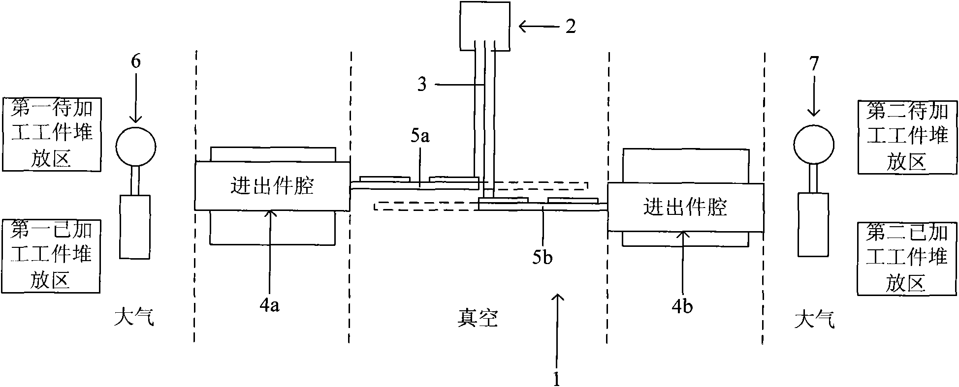
[0060] Such as figure 1 As shown, the vacuum transmission process equipment of this embodiment first includes a vacuum process chamber 1, and a processing device 2 is arranged in the vacuum process chamber 1, and the processing device 2 uses a processing medium 3 to process the workpiece. The processing device 2 is relatively Preferably, the workpiece is processed in a non-contact manner, such as processing the workpiece with an ion beam or plasma. At this time, the processing medium 3 is correspondingly an ion beam or plasma. In addition, the processing device 2 can also be used for heat treatment or annealing of the workpiece. processing equipment, etc.
[0061] The vacuum transfer processing equipment also includes at least two inlet and outlet chambers, such as figure 1 The inlet and outlet chambers 4a and 4b in the inlet and outlet chambers, some of the inlet and outlet chambers are connected to one side of the vacuum process chamber 1, while the rest of the inlet and ou...
Embodiment 2
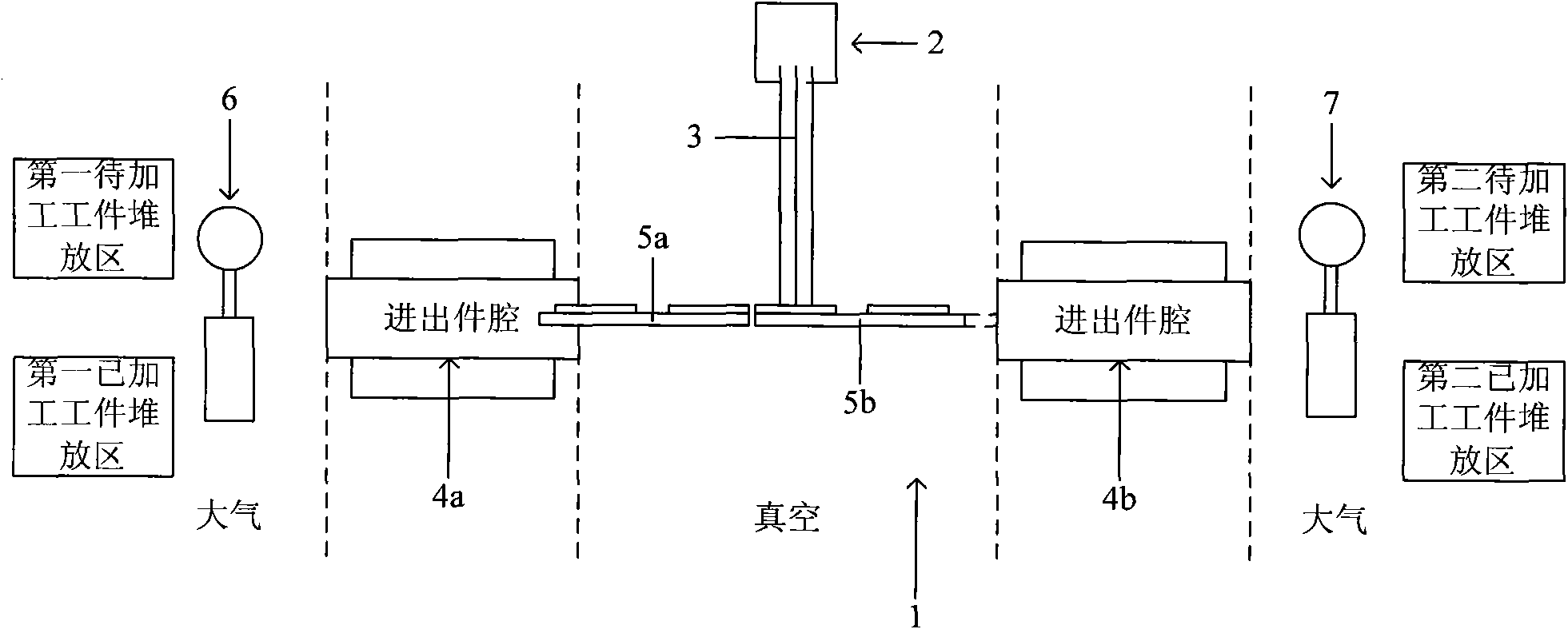
[0080] Such as figure 2 As shown, the difference between the vacuum transmission process equipment in this embodiment and the equipment in Embodiment 1 is only that: in Embodiment 2, the transport platform corresponding to the inlet and outlet cavity located on one side of the vacuum process chamber 1 It is the same as the two-by-two moving plane of the transport platform corresponding to the inlet and outlet cavity located on the other side of the vacuum process chamber 1, for example, in figure 2Among them, the moving planes of the transfer platform 5a and the transfer platform 5b are the same; and the vacuum transfer process method in this embodiment is exactly the same as that in Embodiment 1. Thanks to the above design, for each pair of transmission platforms with the same moving plane, since the workpieces are processed in the same plane, it is possible to completely eliminate the differences in processing strength and processing uniformity between each pair of transmi...
Embodiment 3
[0082] Such as image 3 As shown, the difference between the vacuum transmission process equipment in this embodiment and the vacuum transmission process equipment in Embodiment 1 is only that: in Embodiment 3, each inlet and outlet chamber includes a first chamber and a first chamber. Two chambers, the first chamber of some of the inlet and outlet chambers is connected to one side of the vacuum process chamber, the second chamber is connected to the other side of the vacuum process chamber, and the first chambers of the other inlet and outlet chambers are connected On the other side of the vacuum process chamber, the second chamber communicates with one side of the vacuum process chamber, for example image 3 The inlet and outlet chamber 4a is composed of a first chamber 4aa and a second chamber 4ab, while the inlet and outlet chamber 4b is composed of a first chamber 4ba and a second chamber 4bb.
[0083] The number of first chambers disposed on both sides of the vacuum pro...
PUM
 Abstract
Description
Claims
Application Information
 - R&D Engineer
- R&D Manager
- IP Professional
- Industry Leading Data Capabilities
- Powerful AI technology
- Patent DNA Extraction
Browse by: Latest US Patents, China's latest patents, Technical Efficacy Thesaurus, Application Domain, Technology Topic, Popular Technical Reports.
© 2024 PatSnap. All rights reserved.Legal|Privacy policy|Modern Slavery Act Transparency Statement|Sitemap|About US| Contact US: help@patsnap.com


