Image forming apparatus, image forming method, and computer program
An image and equipment technology, which is applied in the fields of image forming equipment, image forming and computer programs, and can solve problems such as inability to complete output
- Summary
- Abstract
- Description
- Claims
- Application Information
AI Technical Summary
Problems solved by technology
Method used
Image

Examples
no. 1 example
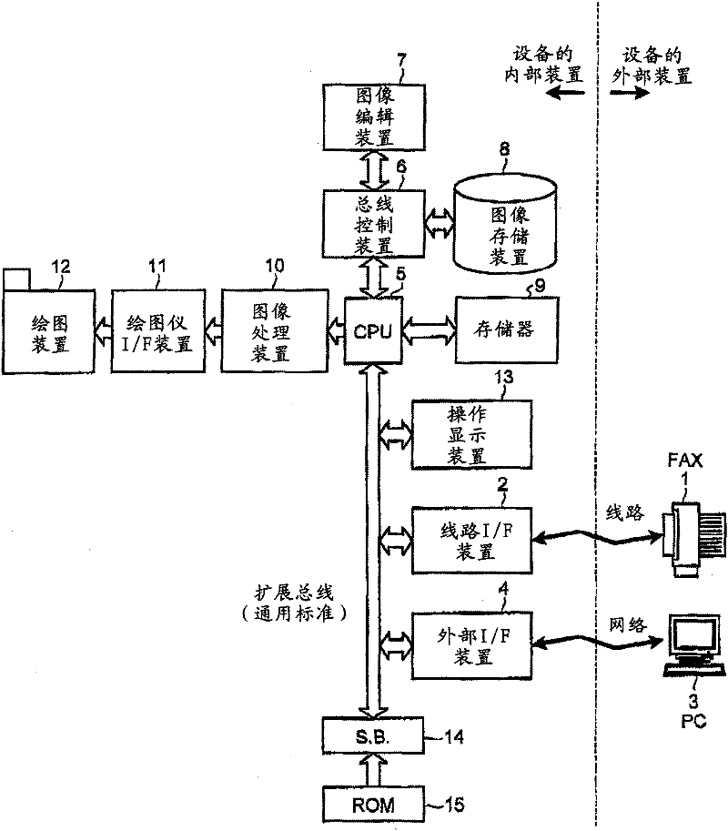
[0021] figure 1 is a block diagram showing a system configuration of an image forming apparatus (hereinafter referred to as a multifunction printer (MFP)) according to the present embodiment. The MFP can send / receive image data to / from a facsimile device (FAX) 1 externally connected to the MFP through a telephone line and a line interface (I / F) device 2 . In addition, the MFP can input / output various control commands and image data from / to a personal computer (PC) 3 externally connected to the MFP via a network and an external I / F device 4 .
[0022] The CPU 5 is a microprocessor that controls the entire MFP. The CPU 5 performs management such as switching between the standard printing mode and the low-cost printing (low-speed printing) mode, calculating the processing time of print jobs, determining the order of print jobs, scheduling low-power time periods scheduled at night, obtaining the current time, etc. Wait.
[0023] The bus control device 6 communicates various dat...
no. 2 example
[0047] Figure 6 is a flowchart showing print mode switching processing according to the second embodiment. exist Figure 5 In the processing sequence shown, the print mode switching is performed by comparing the processing time of the job in the low-cost print mode with the remaining time to elapse before the end time of the night electricity price when additional print jobs are printed during printing in the low-cost print mode . Then, based on the comparison result, the determination unit 102 determines whether the process is to be switched between the low-cost printing mode and the standard printing mode. Therefore, according to the second embodiment, when an additional print job is added to the print job being executed, the determination process ( Figure 5 (step S13)).
[0048] According to the present embodiment, a switching method is explained by which the print job is executed in the low-cost printing mode just before the end time of the nighttime electricity pric...
no. 3 example
[0057] Figure 7 is an explanatory diagram showing a case where the order of the print jobs is not changed when all the stored print jobs are output just before the end time of the nighttime electricity rate.
[0058] Such as Figure 7 As shown, the monochrome document [1] was received at 1:00 am, the full color document [2] was received at 2:15 am, and the monochrome document [3] was received at 3:30 am. If the processing time of each received monochrome document calculated by the printing time estimating unit 103 is 1 minute, and the processing time of the received color document calculated by the printing time estimating unit 103 is 2 minutes, then exactly at 6:56 AM Before heating the heating roller, the print jobs are processed in the order in which the print jobs were stored, that is, in the order of [1], [2], and then [3], and at 7:00 am at the end of the time period in which the nighttime electricity price is applied before completing the print job.
[0059] Assume ...
PUM
 Abstract
Description
Claims
Application Information
 - R&D
- Intellectual Property
- Life Sciences
- Materials
- Tech Scout
- Unparalleled Data Quality
- Higher Quality Content
- 60% Fewer Hallucinations
Browse by: Latest US Patents, China's latest patents, Technical Efficacy Thesaurus, Application Domain, Technology Topic, Popular Technical Reports.
© 2025 PatSnap. All rights reserved.Legal|Privacy policy|Modern Slavery Act Transparency Statement|Sitemap|About US| Contact US: help@patsnap.com