Heater for heating fuel oil by using heat of engine

A technology for engines and heaters, which is applied in the direction of engine components, combustion engines, machines/engines, etc., can solve the problems of complex structure of heating devices, inconvenient installation, etc., achieve obvious fuel saving effects, improve combustion efficiency, and increase output power Effect

Inactive Publication Date: 2012-03-07
黄泳秋
View PDF7 Cites 0 Cited by
  • Summary
  • Abstract
  • Description
  • Claims
  • Application Information

AI Technical Summary

Problems solved by technology

However, the structures of these heating devices are mostly complicated, and it is inconvenient to install them on the basis of the original engine.

Method used


Image

  • Heater for heating fuel oil by using heat of engine
  • Heater for heating fuel oil by using heat of engine

Examples


Embodiment Construction

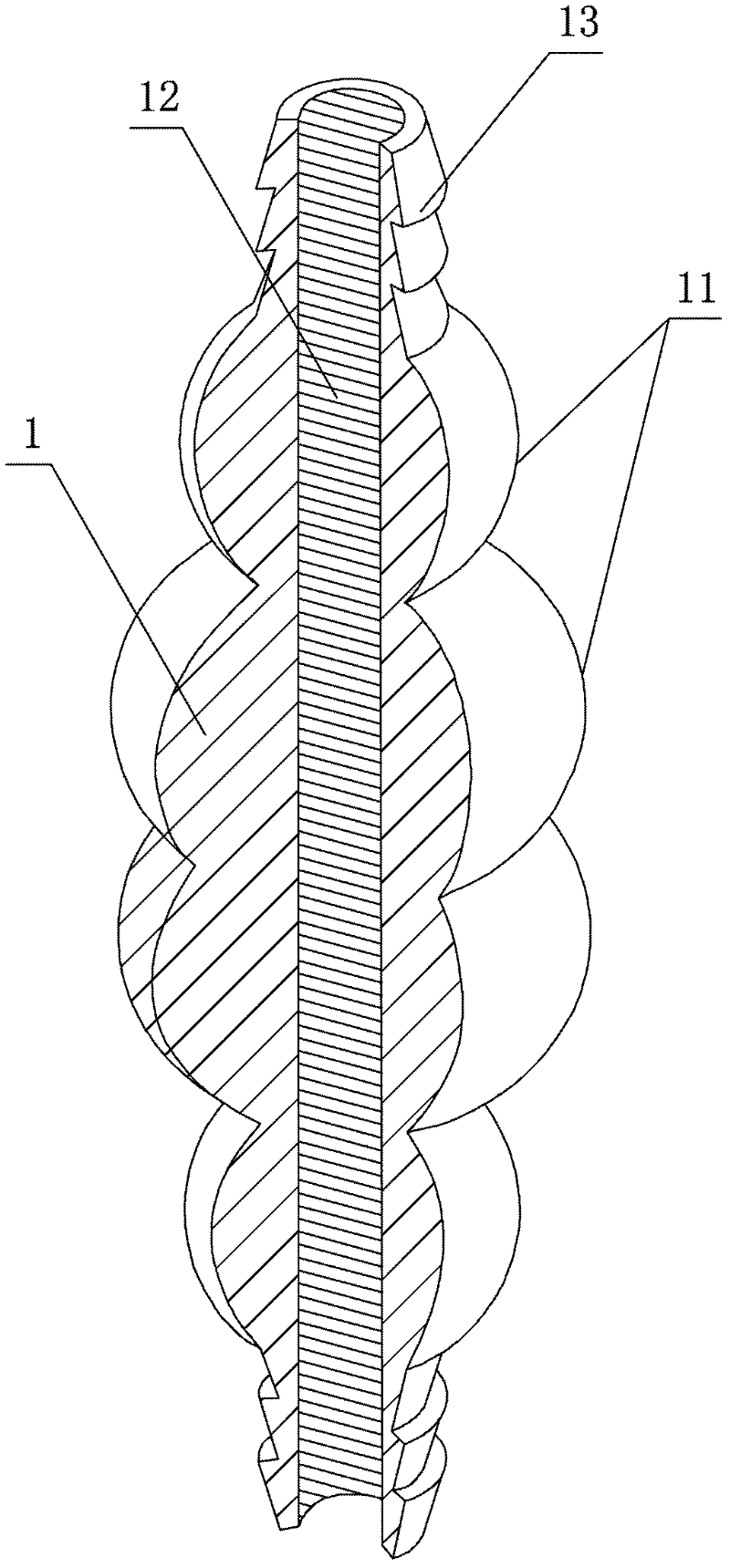
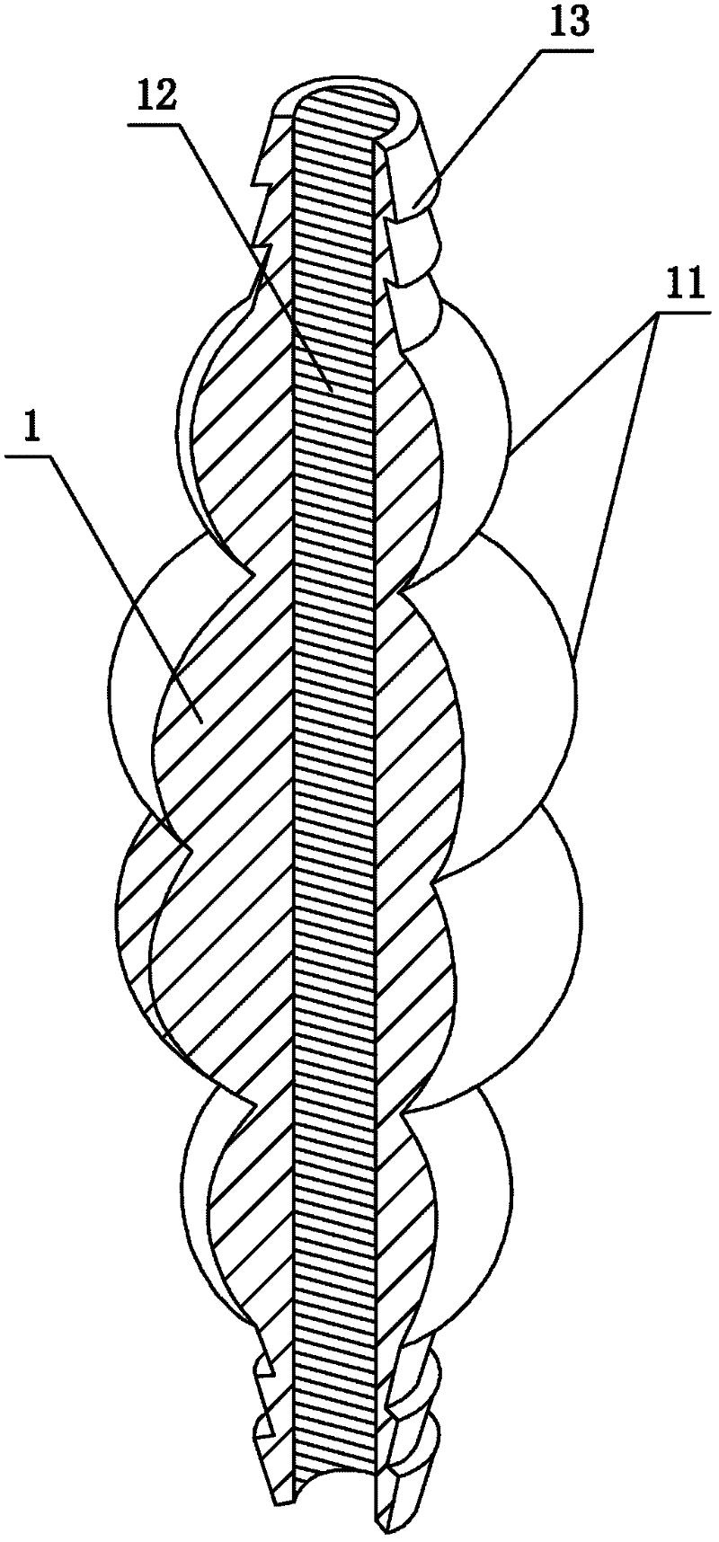
[0008] Such as figure 1 As shown, a heater that uses the heat of the engine to heat fuel oil includes a heat absorber 1 that is divided into several continuous sections that are raised parts 11, and the heat absorber 1 is provided with a fuel oil that passes through each raised section 11. The through hole 12 and the heat absorber 1 are respectively provided with a fuel pipe interface 13 at both ends of the through hole 12 .

[0009] In the actual production of this heater, in order to quickly prototyping and reflect its ease of processing, the raised part 11 is set into a spherical shape, so that it can be used as a heat absorbing body and a heating body for heating fuel oil at the same time, with circumferential consistency . The heater also sets the inner wall of the fuel through hole 12 into a thread shape, so that when the fuel flows through the heater, it flows in a vortex shape, which not only expands the heating area of ​​the fuel, but also increases the distance of t...


PUM


Abstract

The invention discloses a heater for heating fuel oil by using heat of an engine. The heater is characterized by comprising a heat absorber divided into a plurality of continuous protruded parts, wherein a fuel oil through hole penetrating through the protruded parts is formed in the heat absorber, and the heat absorber is respectively provided with a fuel oil pipeline port at two ends of the through hole. By using waste heat of an engine cylinder body, before fuel oil enters the cylinder, the fuel oil is heated and activated, thermal motion of fuel oil molecules is accelerated, the constraint of intermolecular forces of the fuel oil is broken through so that macromolecule groups of the fuel oil are decomposed into micromolecule groups, the fuel can be fully mixed with air and combusted, thus the combustion efficiency of the fuel oil in the engine is increased, the output power of the engine is increased and the purpose of saving the fuel oil can be completely achieved.

Description

technical field [0001] The invention relates to the technical field of fuel engines, in particular to a heater for heating fuel. Background technique [0002] As we all know, before fuel enters the engine, it needs to be sprayed into mist and evaporated, and mixed with air in a certain proportion to form a combustible mixture. Only when the combustible mixture is fully and completely combusted in the cylinder can the engine generate more power and the emission of harmful substances in the exhaust gas can be controlled to a minimum. In fact, the engine cannot completely burn the fuel in the cylinder, because the hydrocarbon molecules in the fuel will form some large molecular clusters, making the innermost hydrocarbon molecules It is quickly discharged out of the cylinder without a chance to mix and burn with oxygen, wasting fuel and becoming the main component of harmful exhaust gas. In order to promote the complete combustion of fuel oil within the detonation period, it i...

Claims


Application Information

Patent Timeline
Patent Type & Authority Applications(China)
IPC IPC(8): F02M31/14
CPCY02T10/12
Inventor 邓经城
Owner 黄泳秋
Why Eureka
Try Eureka