
Vane pump

A vane pump, pump cavity technology, applied in the direction of pumps, pump components, rotary piston pumps, etc., can solve problems such as vane damage

Inactive Publication Date: 2012-02-29
TAIHO INDUSTRIES CO LTD
View PDF4 Cites 7 Cited by
  • Summary
  • Abstract
  • Description
  • Claims
  • Application Information

AI Technical Summary

Problems solved by technology

Moreover, if a large amount of lubricating oil is sucked into the pump chamber, when the vane pump is started next time, an excessive load will be applied to the vane in order to discharge the lubricating oil, and the vane may be damaged.

Method used


Image

  • Vane pump
  • Vane pump
  • Vane pump

Examples


Embodiment Construction

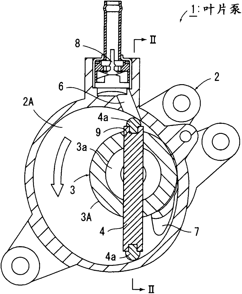
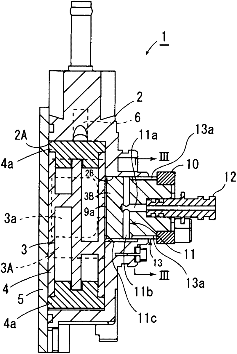
[0031] The invention is described below with respect to the illustrated embodiments, figure 1 , figure 2 The vane pump 1 according to the present invention is shown, and the vane pump 1 is fixed to the side of an engine of an unillustrated automobile to generate a negative pressure to a force multiplying device of an unillustrated brake device.

[0032] This vane pump 1 is provided with: a casing 2 formed with a substantially circular pump chamber 2A, a rotor 3 rotated by a driving force of an engine at a position eccentric with respect to the center of the pump chamber 2A, and The vane 4 that divides the pump chamber 2A into a plurality of spaces, and the cover 5 that closes the pump chamber 2A.

[0033] On the above-mentioned casing 2, an air intake passage 6 communicating with the force-multiplier device of the above-mentioned brake is respectively provided above the pump chamber 2A to attract gas from the force-double device, and an air intake channel 6 is provided below...


PUM


Abstract

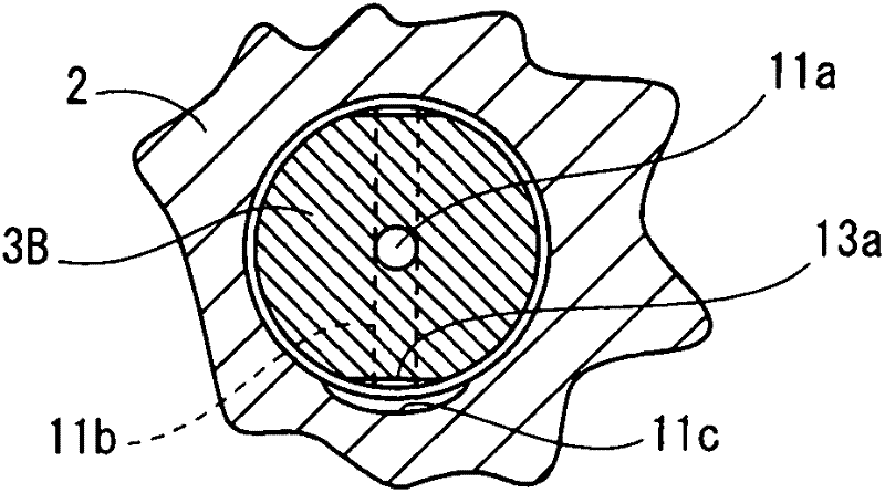
Disclosed is a vane pump (1) wherein lubricant is supplied to a pump chamber (2A) via an axial oil supply port (11a), a diametric oil supply port (11b), and an axial oil supply groove (11c) of an oil supply passage (11). A gas passage (13) is comprised of a gas groove (13a) which is formed in the outer peripheral surface of a shaft (3B) of a rotor (3) and which has an end portion communicating with an outer space. The other end portion of the gas groove is intermittently overlapped with the axial oil supply groove (11c) by the rotation of the rotor, so as to communicate with the axial oil supply groove (11c). The gas passage is comprised of the gas groove (13a) in the shape of a groove, and accordingly, tends not to become clogged in comparison with a conventional apparatus in which the gas passage (13) is comprised of a through-hole, and thus, the flow passage area of the gas passage can be reduced. Therefore, air can be prevented from being introduced from the gas passage into the pump chamber, and the drive torque of an engine can be prevented from increasing.

Description

technical field [0001] The present invention relates to a vane pump, and more specifically, to a vane pump in which an oil supply passage through which lubricating oil flows is formed inside a rotor, and lubricating oil is intermittently supplied into a pump chamber by rotation of the rotor. Background technique [0002] Conventionally, there is known a vane pump (Patent Document 1) that includes a housing having a substantially circular pump chamber, a rotor that rotates at an eccentric position relative to the center of the pump chamber, and rotates the rotor to rotate the pump chamber. The pump chamber is always divided into a plurality of vanes, the oil supply passage intermittently communicated with the pump chamber by the rotation of the rotor, and the pump chamber and the pump chamber when the oil supply passage communicates with the pump chamber by the rotation of the rotor. gas pathways communicating with the external space, [0003] Furthermore, the oil supply pas...

Claims


Application Information

Patent Timeline
Patent Type & Authority Applications(China)
IPC IPC(8): F04C18/344F04C25/02F04C29/02
CPCF04C18/3442F04C25/02F04C29/023F04C2240/20F04C18/344F04C29/02F04C28/06
Inventor 榊原隆一太田原清隆林田喜久治久野祥正
Owner TAIHO INDUSTRIES CO LTD
Learn More