
Naked eye stereoscopic display method based on liquid crystal light valve curtain device

A technology of liquid crystal light valve and naked-eye stereo, which is applied in the direction of stereo system, optics, optical components, etc., can solve the problems such as easy reduction of resolution, and achieve the effect of avoiding easy reduction of resolution, clear display image and strong sense of depth

Inactive Publication Date: 2013-07-17
HEFEI UNIV OF TECH
View PDF3 Cites 0 Cited by
  • Summary
  • Abstract
  • Description
  • Claims
  • Application Information

AI Technical Summary

Problems solved by technology

[0004] The object of the present invention is to provide a naked-eye three-dimensional display method based on a liquid crystal light valve curtain device, so as to solve the problem that the resolution of the existing naked-eye three-dimensional display method is easy to decrease

Method used


Image

  • Naked eye stereoscopic display method based on liquid crystal light valve curtain device

Examples


Embodiment Construction

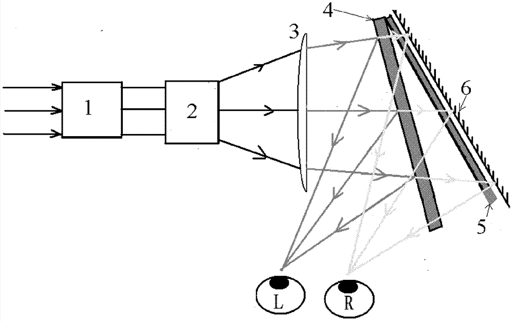
[0013] like figure 1 shown. The three-dimensional display device based on the liquid crystal light valve curtain is composed of a high-frequency image source 1, a light splitting element 2, a lens group 3, a liquid crystal light valve A4, a liquid crystal light valve B5 with a polarizer attached, and a reflector 6. The high-frequency image source 1 and the light-splitting element 2 are all located within one focal length of the lens group 4, and the plane where the liquid crystal light valve A4 is located forms a certain angle with the two light-splitting elements; the liquid crystal light valve B5 and the reflector 6 form a certain angle with the liquid crystal light valve A4 Arranged at an angle, the reflector 6 is located at the rear side of the liquid crystal light valve B5 and placed close to the liquid crystal light valve B5.

[0014] In the method of the present invention. High-frequency image source 1 outputs high-frequency parallax images of left and right eyes (usu...


PUM


Abstract

The invention discloses a naked eye stereoscopic display method based on a liquid crystal light valve curtain device. Left-right eye parallax images at high frequency (usually not less than 120 HZ) are output by a high-frequency image source, and image light rays are parallelly output in a time interleaving way and are distributed in a comb shape through a light splitting component; the images distributed in the comb shape form virtual images through a lens group; and under the cooperation of a liquid crystal light valve A and a liquid crystal light valve B with a polaroid sheet, left eye images are separated from right eye images to achieve stereoscopic display so as to reduce crosstalk.

Description

technical field [0001] The invention relates to the field of stereoscopic display methods, in particular to a naked-eye stereoscopic display method based on a liquid crystal light valve curtain device. Background technique [0002] Several parallax-based naked-eye stereoscopic display methods in the prior art mainly include parallax barrier (front, rear) and lenticular methods. The parallax barrier stereoscopic display technology uses a series of light-shielding stripes arranged in the vertical direction between the backlight module and the LCD panel to form a parallax barrier, which separates the images of the left eye and the right eye, so that 3D images can be obtained, and some programs install the parallax barrier in the LCD front. At present, the parallax barrier is generally realized by liquid crystal, which can control the switch of the parallax barrier, display 2D images when there is no parallax barrier, and display 3D images when there is a parallax barrier. The...

Claims


Application Information

Patent Timeline
Patent Type & Authority Patents(China)
IPC IPC(8): G02B27/26G02F1/1335G02F1/133H04N13/00G02B30/25
Inventor 胡跃辉尹静吕国强吴娟
Owner HEFEI UNIV OF TECH
Learn More