
Full face type pulling plate and clamping piece structure

A full-plane, clamping technology, applied in the field of transformers, can solve problems such as inappropriate processing, unstable structure, unstable clamping, etc., and achieve the effects of reducing processing difficulty, high assembly efficiency, and stable contact surface

Active Publication Date: 2012-02-22
WUXI PUTIAN IRON CORE CO LTD
View PDF3 Cites 8 Cited by
  • Summary
  • Abstract
  • Description
  • Claims
  • Application Information

AI Technical Summary

Problems solved by technology

This kind of connection structure is complex, there is a thickness gap between the drawing plate and the contact surface of the iron core silicon steel sheet and the clamp, this gap must be filled with insulating parts, and the structure is unstable; the processing of the insulating parts is difficult, and the processing If it is not properly adjusted, the force will be uneven between the iron core, the pull plate and the clamp, and the clamp will not be stable, which will cause noise and loss.

Method used


Image

  • Full face type pulling plate and clamping piece structure
  • Full face type pulling plate and clamping piece structure
  • Full face type pulling plate and clamping piece structure

Examples


Embodiment Construction

[0022] The specific embodiments of the present invention will be further described below in conjunction with the accompanying drawings.

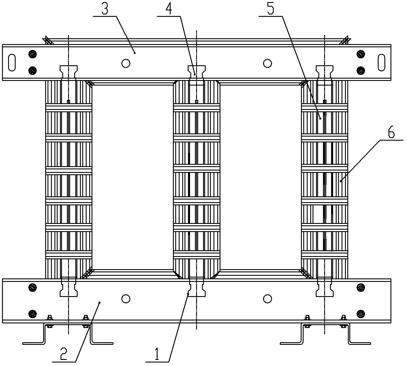
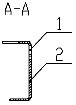
[0023] Figure 1~Figure 8 Among them, it includes card slot 1, lower clip 2, upper clip 3, chuck 4, pull plate 5, iron core 6, long slot 7, notch 8, etc.

[0024] Such as figure 1 As shown, the present invention is a full-plane pull plate clamp structure, which reinforces the core column in the axial direction, clamps and reinforces the laminated iron core into a whole magnetic circuit, and prevents the upper and lower yoke joints of the iron core from exerting force on the iron core. The seam brings damage, which affects the increase of core loss. It includes an upper clamp 3 , a lower clamp 2 and a pull plate 5 . Pull plate 5 has three.

[0025] Such as Figure 2 ~ Figure 4 As shown, the cross-section of the lower clip 2 is groove-shaped, and is formed by flanging steel plates, and the width of the upper flange plate is greater than t...


PUM


Abstract

The invention relates to a full face type pulling plate and clamping piece structure for a transformer iron core. The full face type pulling plate and clamping piece structure comprises an upper clamping piece, a lower clamping piece and a pulling plate, wherein cross sections of the upper clamping piece and the lower clamping piece have a groove shape; both ends of the pulling plate are providedwith chucks; the webs of the upper clamping piece and the lower clamping piece are provided with troughs of which the shapes are matched with those of the chucks; the chucks are clamped on the rear side of the troughs; and the pulling plate, the upper clamping piece and the lower clamping piece are stuck on the same plane of the iron core. In the full face type pulling plate and clamping piece structure, both ends of the pulling plate are provided with the chucks, both ends of the pulling plate are clamped in the troughs of the upper clamping piece and the lower clamping piece in an inlaying way, and the pulling plate, the upper clamping piece and the lower clamping piece are stuck on the same plane of the iron core, so that the contact surface of the clamping pieces and the iron core is more smooth, and a bundling effect on the iron core is relatively good, and the difficulty in processing an insulating material filled in the center of the iron core is reduced. The full face type pulling plate and clamping piece structure is easy to assemble and has high iron core assembly efficiency.

Description

technical field [0001] The invention relates to a transformer, in particular to a full-plane pull-plate clamp structure for a transformer core. Background technique [0002] In the transformer, the iron core clamp plays the role of clamping the silicon steel sheet of the iron core, forming the magnetic field circuit in the transformer, and acting as the internal installation skeleton of the transformer. [0003] The existing iron core clamps mainly include upper clamps, lower clamps and pull plates connecting the upper clamps and lower clamps. The upper clamps and lower clamps are mostly made of profiled channel steel. There are positioning holes on the top, and positioning keys are arranged at both ends of the pull plate, and the positioning keys are fixed in the positioning holes. This kind of connection structure is complex, there is a thickness gap between the drawing plate and the contact surface of the iron core silicon steel sheet and the clamp, this gap must be fill...

Claims


Application Information

Patent Timeline
Patent Type & Authority Applications(China)
IPC IPC(8): H01F27/26H01F41/02
Inventor 蔡子祥王向阳
Owner WUXI PUTIAN IRON CORE CO LTD
Learn More