A steel member assembly method with self-supporting and positioning functions

An assembly method and technology for steel components, which are used in auxiliary devices, metal processing equipment, auxiliary welding equipment, etc.

Active Publication Date: 2022-02-01
中冶(上海)钢结构科技有限公司
View PDF0 Cites 0 Cited by
  • Summary
  • Abstract
  • Description
  • Claims
  • Application Information

AI Technical Summary

Problems solved by technology

The above-mentioned procedures are almost indispensable in the assembly of welded BH steel and the assembly of welded boxes.

Method used


Image

  • A steel member assembly method with self-supporting and positioning functions
  • A steel member assembly method with self-supporting and positioning functions

Examples


Embodiment Construction

[0015] The present invention is further illustrated below by specific examples.

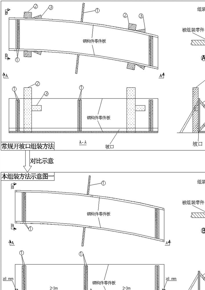
[0016] Such as Figure 1~Figure 2 As shown, a steel component assembly method with its own support and positioning functions;

[0017] Step 1. When cutting the groove or welding gap of the parts to be assembled, leave no less than 8mm long non-cut flanges at the two ends of the parts to be assembled and at a distance of 2~3m;

[0018] Step 2. When assembling the components, the non-cutting flange forms an effective stable contact surface. Further, forming a positioning line on the side of the non-cutting flange at both ends of the component parts also assists in the installation and positioning of the assembly parts. In this way, For the assembly of curved steel members to further increase its stability;

[0019] Step 3. Complete the pair assembly of the components. In this process, no additional use of abutment and wedges to repeatedly adjust the position is required, and the relative contact ...


PUM


Abstract

Specifically, the present invention is a method for assembling steel components with its own support and positioning functions; its feature is: when cutting grooves or welding gaps for the parts of the steel components to be assembled, at the two ends of the parts to be assembled and at a distance of 2 A non-cut flange of not less than 8mm is left at the position of ~3m; when the components are assembled, the non-cut flange forms an effective smooth contact surface, and further, the non-cut flanges at both ends of the component parts The positioning line formed on the side also assists in the installation and positioning of assembly parts. In this way, the stability of the assembly of curved steel components is further increased; the assembly of components is completed, and the process does not need to repeatedly adjust the position with additional abutment and wedges. The method utilizes the reserved flanges of the parts for assembly, so that the installation position of the parts can be precisely controlled, the fixing measures can be reduced, the process can be simplified, and the assembly time can be shortened; at the same time, the welding gap between the part plates can be effectively controlled.

Description

technical field [0001] The invention relates to the field of steel structure assembly, in particular to a steel component assembly method with its own support and positioning functions. Background technique [0002] At present, in the assembly of steel components in the industry, in order to ensure verticality and positioning accuracy. Such as figure 1 As shown, when assembling, it is usually first to add the abutment of the assembly parts on the assembly tire frame, then hang the parts to the corresponding position and then add wedges to gradually adjust the verticality and positioning position of the parts. Add support welding to fix the parts on the side of the assembled parts, so that it is not easy to shift. The above-mentioned procedures are almost indispensable when assembling and welding the BH section steel and assembling and welding the box body. If the assembled parts need to be grooved or welded backing plates are added to leave welding gaps, the assembled par...

Claims


Application Information

Patent Timeline
Patent Type & Authority Patents(China)
IPC IPC(8): B23K37/04
CPCB23K37/04
Inventor 李章龙王伟张璐杨洋彭刚
Owner 中冶(上海)钢结构科技有限公司
Why Eureka
Try Eureka