Mobile pedal

A movable, foot pedal technology, applied in foot start device, control device, transportation and packaging, etc., can solve the problems of small U-shaped seat gap, difficult U-shaped seat fixing, difficult welding, etc., to prevent sliding, The effect of reducing safety hazards and reducing requirements for experience and competence

Inactive Publication Date: 2013-09-11
李耀强
View PDF5 Cites 0 Cited by
  • Summary
  • Abstract
  • Description
  • Claims
  • Application Information

AI Technical Summary

Problems solved by technology

[0003] In my patent No. 201020193301.8, a self-adaptive pedal is disclosed. The working rod and the pedal are connected through a U-shaped seat, which can automatically adjust the angle between the pedal and the working rod to keep the sole of the foot in line with the working rod. The lack of stability of the contact surface between the pedals is that it is difficult to fix the U-shaped seat on the pedal, usually by welding, but the gap in the middle of the U-shaped seat is small, and welding is difficult

Method used


Image

  • Mobile pedal
  • Mobile pedal
  • Mobile pedal

Examples


Embodiment Construction

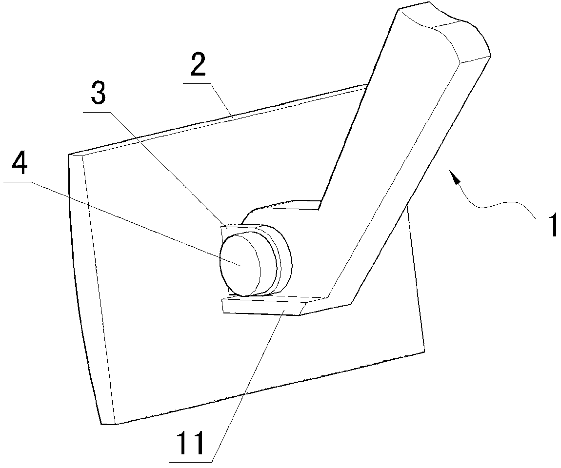
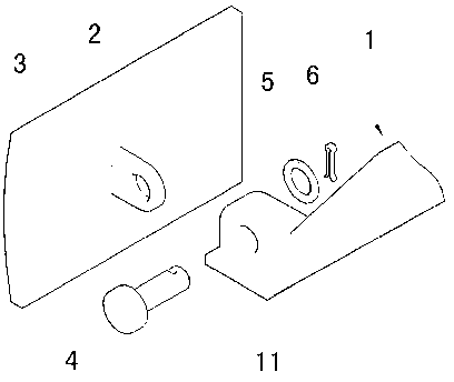
[0017] Such as figure 1 and figure 2 As shown, a movable pedal is composed of a working rod 1, a pedal 2, an ear 3, a fixed shaft 4, a washer 5, and a cotter pin 6, and one end of the ear 3 is fixed on the pedal 2 The other end is semicircular, and a mounting hole is provided at the center of the semicircle; the bottom side of the end of the working rod 1 is provided with a stop platform 11 .

[0018] The upper end of the working rod 1 is in the shape of a quarter circle, and a mounting hole is arranged at the center of the circle. When the pedal 2 and the working rod 1 move relatively, the pedal 2 rotates around the upper quarter of the fixed shaft 4 end.

[0019] The fixed shaft 4 passes through the mounting hole on the lug 3 and the mounting hole on the working rod 1 to connect the working rod 1 and the lug 3 together.

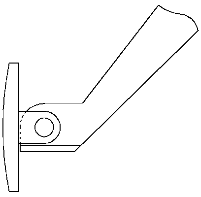
[0020] Such as image 3 As shown, in the static state, the stop platform 11 of the working rod 1 is against the lower edge of the lug 3, so that the p...


PUM


Abstract

A novel pedal is composed of a working beam 1, a pedal 2, a lug 3, a fixing shaft 4, a gasket 5, a split pin 6, an adjusting screw 7 and a spring 8. A stop block 11 arranged on the lower portion of the tail end of the working beam 1 is provided with a screw through hole, and the adjusting screw 7 penetrates out of the spring 8 to be screwed in the screw through hole in the stop block 11. By arrangement the stop block on the lower portion of the working rod and the adjusting screw on the stop block, an operator can adjust angles of the pedal in an idle state as required, and the angles between the pedal and the working rod can be automatically adjusted to keep a stable contact surface between a sole and the pedal, so that requirements of the operators for experience and ability are lowered.

Description

technical field [0001] The invention relates to the field of automobiles, machinery and the like that need to use pedals, and belongs to the pedal optimization technology. Background technique [0002] Most of the currently used pedals, such as car brakes and clutch pedals, are connected to the working rod by direct fixing, that is, the angle between the pedal and the working rod cannot be changed. of. Especially for hanging pedals, as the position of the pedals changes during work, the angle between the pedals and the soles of the operator is also constantly changing. The contact area will become less and less, and it is very easy to cause the danger of sliding. If want to keep the stability of the contact surface of pedal and sole, just must adjust the contact angle of sole and pedal at random to adapt to change. In fact, due to the characteristics of this hanging structure and the characteristics of the physiological structure of the human body, it is impossible to mee...

Claims


Application Information

Patent Timeline
Patent Type & Authority Applications(China)
IPC IPC(8): B60K23/02B60T7/06
Inventor 李耀强
Owner 李耀强
Why Eureka
Try Eureka