Injection impeller burner

A burner and injection technology, applied in the direction of burners, gas fuel burners, combustion methods, etc., can solve the problems of low combustion thermal efficiency, high exhaust gas emissions, insufficient and uniform mixing of gas and injected air, etc. , to achieve good effect, improve combustion heat efficiency, easy manufacture and application promotion

Inactive Publication Date: 2012-02-22
王萍 +1
View PDF8 Cites 10 Cited by
  • Summary
  • Abstract
  • Description
  • Claims
  • Application Information

AI Technical Summary

Problems solved by technology

[0011] The problem that the present invention aims to solve in the ejector burner is: when the ejector burner is burning, the gas and the air to be ejected cannot be fully and evenly mixed, so that the amount of gas and the theoret...

Method used


Image

  • Injection impeller burner
  • Injection impeller burner
  • Injection impeller burner

Examples


Embodiment Construction

[0017] The present invention will be described in detail below in conjunction with the accompanying drawings.

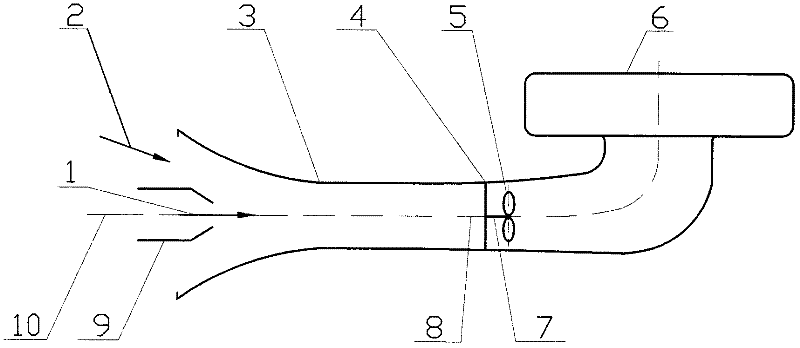
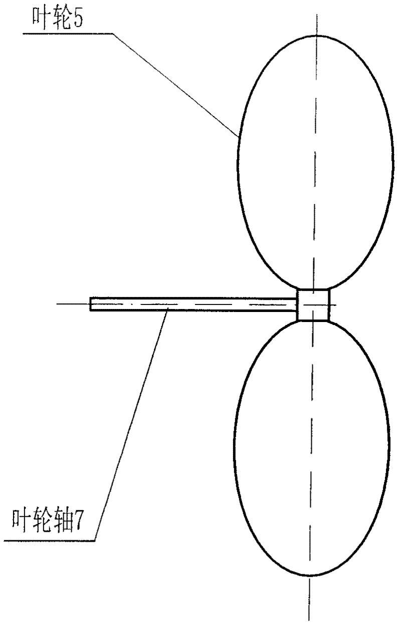
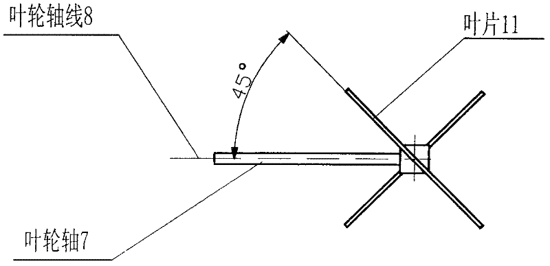
[0018] like figure 1 , figure 2 , image 3 As shown, the injection impeller burner includes a nozzle 9, an injection pipe 3, an impeller 5 and a combustion head 6. A shaft support 4 is arranged inside the injection pipe 3, and an impeller shaft 7 is arranged on the shaft support 4. The impeller shaft 7 is provided with an impeller 5, the impeller 5 can rotate freely relative to the shaft support 4, the injection tube 3 is fixedly connected to the shaft support 4, and the included angle between the blade 11 on the impeller 5 and the impeller axis 8 is 45° °, the impeller axis 8 coincides with the centerline 10 of the ejector tube.

[0019] Two impellers 5 may be arranged on the impeller shaft 7 .

[0020] The shaft support 4 can be repeatedly provided at intervals in the injection tube 3 , the shaft support 4 is provided with an impeller shaft 7 , and the impelle...


PUM

PropertyMeasurementUnit
Angleaaaaaaaaaa

Abstract

The invention discloses an injection impeller burner, and in particular relates to a civil gas cooker. The burner comprises a spray pipe (9), an injection pipe (3), an impeller (5) and a burning head (6), wherein a shaft bracket (4) is arranged in the injection pipe (3) and provided with an impeller shaft (7); the impeller (5) is arranged on the impeller shaft (7) and can freely rotate relative to the shaft bracket (4); the injection pipe (3) is fixedly connected with the shaft bracket (4); and an impeller axis (8) is overlapped with an injection pipe central line (10). When gas (1) at a certain flow velocity is injected from the spray pipe (9) and enters the injection pipe together with injected air (2) simultaneously to push the impeller (5) jointly to quickly stir in a rotary mode, so that the gas (1) and the air (2) are fully and uniformly mixed at the moment of passing through the impeller (5), and the gas and the injected required theoretical air are distributed in each burning hole of the burning head in the same ratio and enter the burning head (6) to be burnt; therefore, the burning heat efficiency of the injection burner is obviously improved.

Description

Technical field: [0001] The invention relates to an ejector impeller burner, which is mainly used in burners of household gas stoves, commercial gas stoves (boxes), household gas water heaters and the like. Background technique: [0002] According to the way of air intake, burners can be divided into two categories: one is injection burner, and the other is blast burner. When the gas heat flow rate is too large, the injection burner is bulky and heavy, while the blast burner is relatively small in size, and the blast burner is often used in large industrial boilers. [0003] In 1855, Bunsen invented an ejector burner (or atmospheric burner), which is the commonly used Bunsen burner in the laboratory. This ejector burner has a simple structure. It mainly consists of a gas nozzle, an ejector The tube and the combustion head are composed of three parts. Its working principle is: the gas is injected from the nozzle at a certain flow rate under a certain pressure, and the gas ab...

Claims


Application Information

Patent Timeline
IPC IPC(8): F23D14/02F23D14/64
Inventor 王平程继波
Owner 王萍
Why Eureka
Try Eureka