
Pretensioning clamp for heat treated steel bars with high ratio of tensile strength to yield point and application method thereof

A technology of steel bars and fixtures, applied in the processing of building materials, building reinforcements, structural elements, etc., to achieve the effects of high anchorage efficiency coefficient, prevention of premature fracture, and reliable self-anchoring performance

Inactive Publication Date: 2012-02-22
CABR TECH CO LTD +1
View PDF5 Cites 17 Cited by
  • Summary
  • Abstract
  • Description
  • Claims
  • Application Information

AI Technical Summary

Problems solved by technology

However, there is currently no ready-made fixture in our country that can realize the tension and anchorage of this steel bar.

Method used


Image

  • Pretensioning clamp for heat treated steel bars with high ratio of tensile strength to yield point and application method thereof
  • Pretensioning clamp for heat treated steel bars with high ratio of tensile strength to yield point and application method thereof
  • Pretensioning clamp for heat treated steel bars with high ratio of tensile strength to yield point and application method thereof

Examples


Embodiment 1

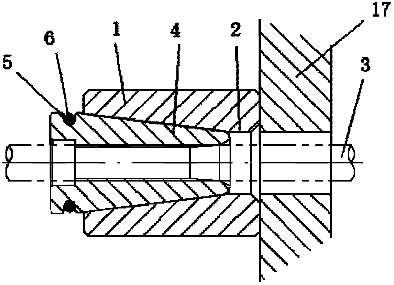
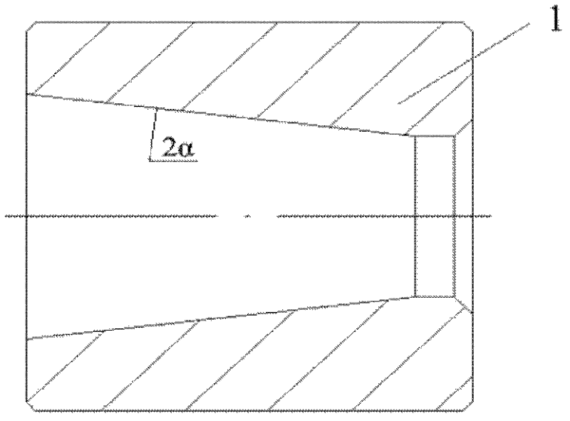
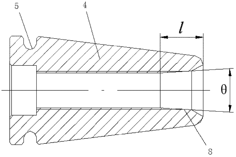
[0025] Such as figure 1 , figure 2 As shown, the present embodiment includes a cylindrical anchor ring 1, the inner diameter of the anchor ring 1 is a tapered hole 2, the cone angle 2α of the tapered hole 2=14°, and the cone angle can vary within 11°-15°. In the tapered hole 2, three clips 4 (such as image 3 , Figure 4 As shown), the conical angles of the outer cone surfaces of the combined three clips 4 are 5' to 30' larger than the conical angles of the taper holes 2, and the outer walls of the big ends of the combined three clips 4 are provided with a circle of grooves 5 , the groove 5 is provided with an O-ring 6 that connects the three clips 4 into one (such as figure 1 shown). Such as Figure 5 As shown, the inner walls of the three clips 4 are provided with screw teeth 7, the radial section of the screw teeth 7 is zigzag, the tooth tip angle of the screw teeth 7 is γ, 76°≤γ≤78°, the front edge of the screw teeth 7 The angle is β, 69°≤β≤71°, and the pitch of the...

Embodiment 2

[0032] Such as Image 6 As shown, this embodiment includes a cylindrical anchor ring 9 , and a section of tapered hole 10 and a section of straight hole 11 connected with the tapered hole 10 are arranged in the anchor ring 9 . The port of the straight hole 11 is provided with three inner convex bayonets 12 (such as Figure 7 , Figure 8 shown), in the taper hole 10, three clips 4 that are identical to each other at 120° are provided in the taper hole 10, and grooves 5 are set on the outer wall of the big end of the three clips 4, and O is arranged in the groove 5. Type sealing ring 6. A spring 13 is arranged at the end of the large end of the three clips 4, and a gland 14 is arranged at the other end of the spring 13. The port of the gland 14 is provided with three pairs of bosses that cooperate with the inner convex bayonet 12 on the anchor ring 9. 15, 16 (such as Figure 9 , Figure 10Shown), and each pair of bosses 15,16 is a high, a low. When in use, the spring 13 is...


PUM

PropertyMeasurementUnit
Pitchaaaaaaaaaa

Abstract

The invention relates to a pretensioning clamp for heat treated steel bars with a high ratio of tensile strength to yield point and an application method thereof. The clamp is characterized in that: the clamp comprises a cylinder-shaped anchor ring; the internal diameter of the anchor ring is a taper hole; three clamping pieces mutually forming an angle of 120 degrees are provided in the taper hole; the outer wall of the big-head end of the clamping pieces is provided with a concave groove; an O-shaped sealing ring is arranged in the concave groove to allow the three clamping pieces to connect and form an integral body; the inner wall of each clamping piece is provided with screw teeth, and a radial cross section of the screw teeth is of a zigzag shape. The invention enables anchoring of steel bars with high ratio of tensile strength to yield point during tensioning to be well realized; the clamp has a great clamping force on the steel bars and high anchoring efficiency, and is repeatedly usable. The clamp can be widely used in pretensioning construction of prestressed concrete in the constructional field.

Description

technical field [0001] The invention relates to a tensioning fixture and a using method thereof, in particular to a heat-treated high-strength yield ratio steel bar (high-strength PC steel bar) pretensioning fixture used in prestressed concrete pretensioning construction and a using method thereof. Background technique [0002] At present, prestressed steel bars in my country mainly use high-strength steel wires and steel strands of high-carbon steel series, and their standard strength values ​​are 1570MPa to 1860MPa. However, pickling is required in the production process of high-strength steel wires and steel strands, which causes environmental pollution. In order to avoid pickling and reduce environmental pollution, China Iron and Steel Research Institute Technology Group Co., Ltd. has successfully developed heat-treated high-strength yield ratio steel bars for prestressed concrete, which use low-alloy steel wires to replace high-strength steel wires and steel strands afte...

Claims


Application Information

Patent Timeline
IPC IPC(8): E04C5/12E04C5/08E04G21/12
Inventor 朱莹陈茜张强
Owner CABR TECH CO LTD
Learn More