
Emergency brake control device and emergency brake control method for automatic vehicle driving robot

An emergency braking and automatic driving technology, applied in the direction of automatic starting device, brake, etc., can solve the problem of not being able to adjust the control scheme in real time, and achieve the effect of convenient installation and disassembly, high control accuracy and wide range of applicable models.

Active Publication Date: 2013-03-27
北京踏歌智行科技有限公司
View PDF7 Cites 0 Cited by
  • Summary
  • Abstract
  • Description
  • Claims
  • Application Information

AI Technical Summary

Problems solved by technology

But because this point brake depends on the mechanical structure that has been processed to decompress, the diameter of the effusion hole has been fixed, and there is no feedback signal from the wheel and the brake pedal (that is, it is an open-loop control), so this point brake When applied to autonomous driving robots, it is impossible to achieve ideal results under various driving conditions, and the control scheme cannot be adjusted in real time according to different vehicle states, and the same process can only be completely repeated during the braking process.

Method used


Image

  • Emergency brake control device and emergency brake control method for automatic vehicle driving robot
  • Emergency brake control device and emergency brake control method for automatic vehicle driving robot
  • Emergency brake control device and emergency brake control method for automatic vehicle driving robot

Examples


Embodiment Construction

[0038] The present invention will be described in detail below in conjunction with the accompanying drawings and embodiments.

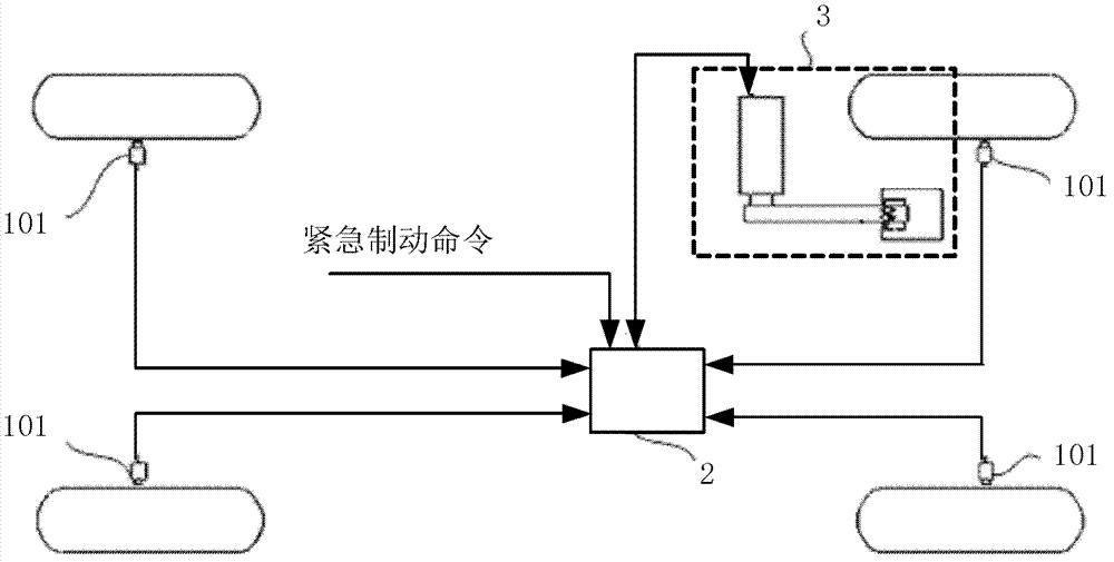
[0039] like figure 1 As shown, the emergency braking control device for a vehicle automatic driving robot mainly includes a vehicle running state detection unit 1, a control unit 2 and an execution unit 3, such as figure 1 shown, as figure 2 shown.

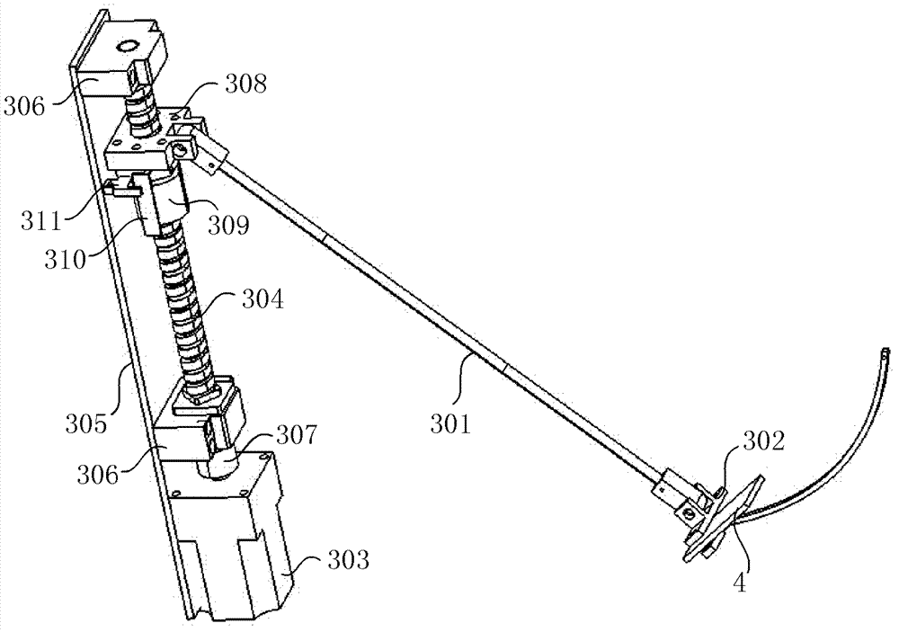
[0040] The execution unit 3 is the execution device of the emergency braking control device of the present invention, such as image 3As shown, it includes a brake machine leg 301 , a pedal connecting plate 302 , a driving motor 303 , a lead screw 304 and a mounting plate 305 . Wherein, the servo motor is fixedly installed on the mounting plate 305 as the driving motor 303 . Both ends of the lead screw 304 are sleeved with a support frame 306 , and the lead screw 304 can rotate freely in the two support frames 306 . The two supporting frames 306 are fixed on the mounting plate 305 , and the lead scr...


PUM


Abstract

The invention discloses an emergency brake control device and an emergency brake control method for an automatic vehicle driving robot. The emergency brake control device comprises a vehicle running state detecting unit, a control unit and an executing unit, wherein the vehicle running state detecting unit is used for acquiring the wheel speed information of each wheel and transmitting the wheel speed information to the control unit; the control unit is used for receiving the wheel speed information transmitted by the vehicle running state detecting unit, analyzing and processing the wheel speed information to obtain the current running state of a vehicle, and controlling an actuating mechanism to perform emergency brake; the braking operation process of the actuating mechanism under the control of the control unit comprises increasing the braking force till the wheel speed of the vehicle is non-uniform or a wheel tends to lock, decreasing the braking force, increasing the wheel speed, and increasing the braking force; and the process is performed circularly till the vehicle stops running. The invention has the advantages that: the automatic driving robot in which the emergency brake device is arranged can be used for quickly and safely braking an ABS (Antilock Brake System)-free vehicle to simulate the actions of repeatedly treading and releasing a brake pedal of a driver for preventing the wheels from being locked in the braking process.

Description

technical field [0001] The invention relates to the field of braking control of vehicles, in particular to an emergency braking control device and control method for a vehicle automatic driving robot. Background technique [0002] The self-driving robot for vehicle testing is an industrial robot that is installed in the cab and operates instead of a human driver in vehicle testing. [0003] Since Japan's Ono Sokki Co., Ltd. successfully developed the world's first self-driving robot in 1994, German SCHENCK, STAHLE, Volkswagen, British MIRA, Froude Consine, Anthony Best Dynamics and American Chrysler have all developed A self-driving robot for automotive performance testing. In China, the DNC-I and DNC-II self-driving robots with independent intellectual property rights have been jointly developed by Southeast University and the Technology Center of Yuejin Group. The self-driving robot can be applied to road condition tests and drum emission tests. At the same time, it can...

Claims


Application Information

Patent Timeline
Patent Type & Authority Patents(China)
IPC IPC(8): B60T8/176B60T7/12
Inventor 余贵珍李芹康乐俞志华
Owner 北京踏歌智行科技有限公司
Learn More