Eureka AIR delivers breakthrough ideas for toughest innovation challenges, trusted by R&D personnel around the world.

Punching machine head

A machine head and collet technology, applied in the direction of presses, heat exchange equipment, manufacturing tools, etc., can solve the problems of high scrap rate, heat sink installation does not meet the heat dissipation requirements of magnetron, and mismatches, so as to improve the success rate , Reduce production precision, improve the effect of qualified rate

Active Publication Date: 2012-02-22
GUANGDONG GALANZ GRP CO LTD
View PDF7 Cites 0 Cited by
  • Summary
  • Abstract
  • Description
  • Claims
  • Application Information

AI Technical Summary

Problems solved by technology

[0002] The existing stamping head includes a collet cover and a collet, the collet is hoisted in the collet cover, and the setting ring is installed in the collet. It is fixed, and the diameter of the installation hole of the heat sink is also constant. When the diameter of the heat dissipation hole produces an error in the manufacturing process, it is bound to be inconsistent with the matching ring, resulting in that the installation of the heat sink does not meet the requirements of the magnetron. Thermal requirements, high scrap rate

Method used


Image

  • Punching machine head
  • Punching machine head
  • Punching machine head

Examples


Embodiment Construction

[0018] The present invention will be described in further detail below in conjunction with the accompanying drawings and embodiments.

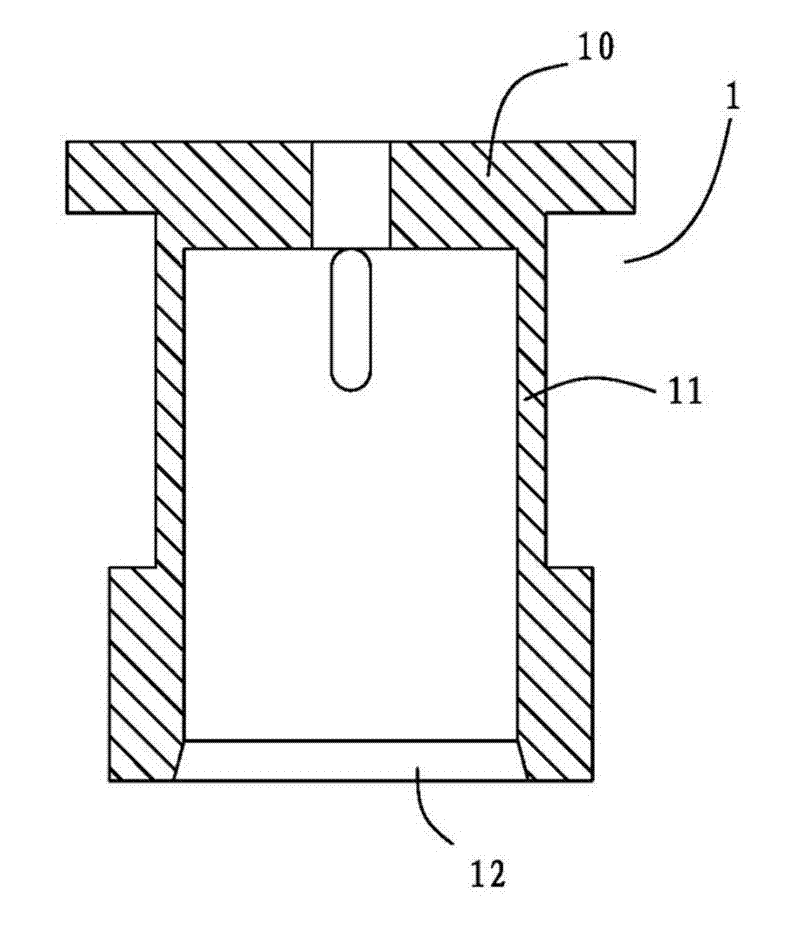
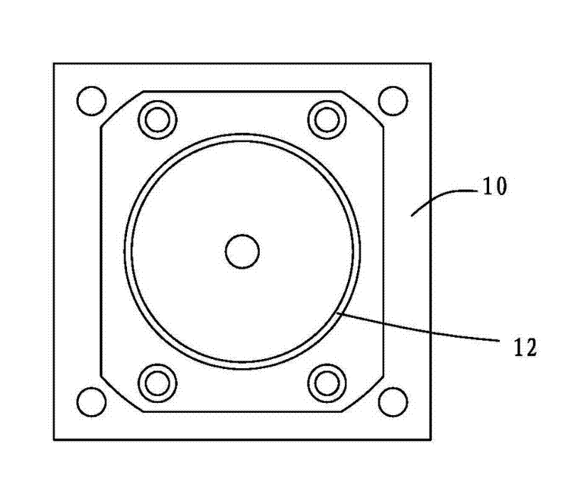
[0019] A stamping machine head, including a collet sleeve 1 and a collet 2, combined with figure 1 , figure 2 , The collet sleeve 1 includes a mounting surface 10 , a ring of walls 11 formed around the mounting surface 10 , and a ring of lower ports 12 surrounded by the wall 11 .

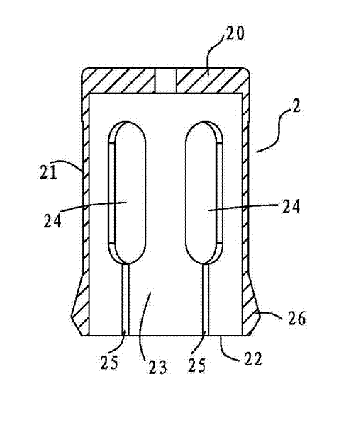
[0020] combine Figure 3 to Figure 5 , the chuck 2 includes a connecting end face 20, a circle of side walls 21 formed around the periphery of the end face 20, and a clamping port 22 surrounded by the side wall 21, and the inner chamber 23 of the chuck 2 passes through the clamping port 22 outward Extending, the side wall 21 is provided with six long grooves 24 penetrating the inner surface and the outer surface of the side wall side by side along the circumferential direction, the long grooves 24 are separated from each other, and the long grooves 24 extend alon...


PUM


Abstract

The invention relates to a punching machine head for punching equipment. The punching machine head comprises a clamping head sleeve and a clamping head. The clamping head is inserted from the lower port of the clamping head sleeve and hung in the clamping head sleeve body. The clamping head and the clamping head sleeve mutually move along the axial direction. The clamping head comprises a connection end face, a ring of side wall and a clamping port. A plurality of long grooves passing through the inside surface and the outside surface of the side wall are arranged on the side wall in a row along a circumferential direction. The long grooves are separated from each other. The long grooves extend along the length direction of the side wall. One ends of the long grooves are far away from theconnection end face. The other ends of the long grooves extend out of the clamping port through a breakage gap on the side wall. The width of the breakage gap is less than that of the long grooves. The side wall at four sides of the clamping port is thickened outwardly to form a ring of bump. The bump is rubbed with the lower port of the clamping head sleeve so that the diameter of the clamping port is reduced. The punching machine head disclosed by the invention is simple and rational in structural design; the production precision of installation aperture of heat dissipation sheets is reduced; the punching installation success rate is also increased; and the yield of magnetrons is further increased.

Description

technical field [0001] The invention relates to a stamping head for stamping equipment. Background technique [0002] The existing stamping head includes a collet cover and a collet, the collet is hoisted in the collet cover, and the setting ring is installed in the collet. It is fixed, and the diameter of the installation hole of the heat sink is also constant. When the diameter of the heat dissipation hole produces an error in the manufacturing process, it is bound to be inconsistent with the matching ring, resulting in that the installation of the heat sink does not meet the requirements of the magnetron. Heat dissipation requirements, high scrap rate. Contents of the invention [0003] Therefore, the object of the present invention is to provide a stamping head with variable diameter of the clamping port, conformable tooling to be stamped and significantly improved yield of stamped workpieces. [0004] The purpose of the present invention is achieved like this. [0...

Claims


Application Information

Patent Timeline
IPC IPC(8): B21D53/02B30B15/00
Inventor 张文亮
Owner GUANGDONG GALANZ GRP CO LTD
Why Eureka
Eureka Blog
Learn More