
Corrugated plate punching device

A stamping device and corrugated plate technology, applied in the field of punches, can solve problems such as unsatisfactory stamping effect, difficulty in setting positioning tools, and inability to guarantee accuracy, etc., to achieve good practical value, improve work efficiency, and simple structure

Inactive Publication Date: 2012-02-22
MINGGUANG JIAYI ELECTRIC CONTROL TECH
View PDF10 Cites 7 Cited by
  • Summary
  • Abstract
  • Description
  • Claims
  • Application Information

AI Technical Summary

Problems solved by technology

[0003] The stamping block of the existing stamping equipment is usually directly fixed on the slider, and it is difficult to set up positioning tools without positioning tools. When performing stamping operations, the operator holds a flat plate under the stamping block, and multiple on the slider The stamping blocks are punched down together. Since there is no effective positioning tool, if the operator is negligent, the stamping effect will not be ideal, and it may even lead to stamping failure.
Therefore, the accuracy of this method that is completely controlled by humans cannot be guaranteed.

Method used


Image

  • Corrugated plate punching device
  • Corrugated plate punching device

Examples


Embodiment Construction

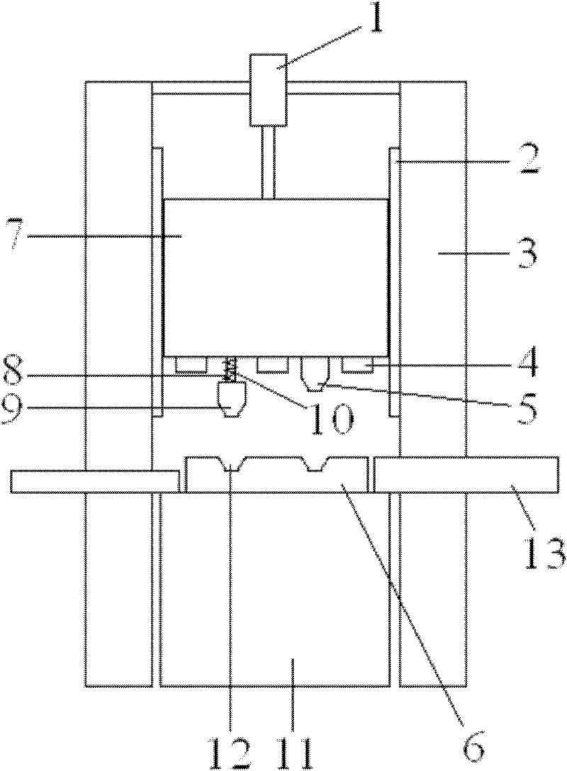
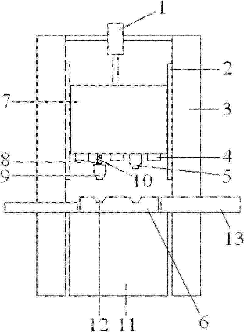
[0012] see figure 1 , a corrugated plate stamping device, including a bracket 3, two parallel vertical guide rails 2 are arranged on the bracket 3, and a slider 7 is installed on the two parallel vertical guide rails 2 through sliding fit, and is located on the two A cylinder 1 is installed on the support above the parallel vertical guide rail 2, and the front end of the piston rod of the cylinder 1 is fixedly connected with the end of the slide block 7; Guide rod 8, the bottom end of guide rod 8 is fixedly welded with left stamping block 9, is covered with spring 10 on the guide rod 8, and the bottom that is positioned at the slide block 7 right side of left stamping block 9 is fixedly installed with right stamping block 5; The bottom of right stamping block 9,5 is provided with workbench 11, and lower mold 6 is fixedly installed on the workbench 11, and lower mold 6 is respectively provided with two die cavities 12, and left and right stamping block 9,5 are positive respecti...


PUM


Abstract

The invention discloses a corrugated plate punching device, which comprises a bracket. Two parallel vertical guide rails are arranged on the bracket. A sliding block is installed on the bracket in a sliding matched manner. A cylinder is installed on the bracket above the two parallel vertical guide rails. The front end of the piston rod of the cylinder is fixedly connected with the end of the sliding block. An opening is arranged at the bottom of the sliding block. A guide rod is installed in the opening in a sliding matched manner. A left punching block is fixedly welded at the bottom of the guide rod. A spring is sleeved on the guide rod. A right punching block is fixedly installed at the bottom of the sliding block at the right side of the left punching block. Pressure blocks are respectively arranged between the left punching block and the right punching block and outside the left punching block and the right punching block. A lower forming mould is just below the left punching block and the right punching block. The device disclosed by the invention is simple in structure; the device can be used for well locating after completing a previous punching stroke and before carrying out a subsequent punching stroke; the punching precision of corrugated plates is increased; simultaneously, the working efficiency is also increased; the defective percentage is reduced; and the device has good practical value.

Description

technical field [0001] The invention relates to the field of punches, in particular to a corrugated plate punching device. Background technique [0002] The punch is also called punch, upper die, male die, punching needle, etc. The punch is a metal part installed on the stamping die. It is used in direct contact with the material to deform and cut the material. [0003] The stamping block of the existing stamping equipment is usually directly fixed on the slider, and it is difficult to set up positioning tools without positioning tools. When performing stamping operations, the operator holds a flat plate under the stamping block, and multiple on the slider The stamping blocks are punched down together, because there is no effective positioning tool, if the operator is negligent, the stamping effect will not be ideal, and even stamping failure will result. Therefore, the accuracy of this method that is completely controlled by humans cannot be guaranteed. Contents of t...

Claims


Application Information

Patent Timeline
Patent Type & Authority Applications(China)
IPC IPC(8): B21D13/02
Inventor 李兵
Owner MINGGUANG JIAYI ELECTRIC CONTROL TECH
Learn More