
IGBT (Insulated Gate Bipolar Translator) driving circuit for novel high-frequency high-voltage switching power supply

A high-frequency, high-voltage, switching power supply technology, applied to electrical components, output power conversion devices, etc., can solve problems such as small power factor, long response time, and susceptibility to interference, and achieve suppression of high-frequency parasitic oscillations, turn-on and turn-off Low power consumption and reduced mutual interference

Inactive Publication Date: 2012-02-15
CHANGSHU YINGNA ENERGY TECH
View PDF0 Cites 5 Cited by
  • Summary
  • Abstract
  • Description
  • Claims
  • Application Information

AI Technical Summary

Problems solved by technology

At present, most of the electrostatic precipitators used in my country are powered by industrial frequency power supplies, which have obvious disadvantages such as low dust removal efficiency, high energy consumption, small power factor, and long response time.
The high-frequency high-voltage electrostatic dust removal power supply overcomes the shortcomings of the power frequency switching power supply. It can provide almost flat corona voltage and fast response time, and has obvious advantages such as high dust removal efficiency, small resistance loss, high temperature resistance, and large flue gas treatment capacity. , so it has a good application prospect. The core of the high-frequency high-voltage switching power supply is the inverter circuit using IGBT as the switching device. Most of the IGBT drive circuits in the existing high-power switching power supply applications are extremely susceptible to interference, safety and stability. low disadvantage

Method used


Image

  • IGBT (Insulated Gate Bipolar Translator) driving circuit for novel high-frequency high-voltage switching power supply

Examples


Embodiment Construction

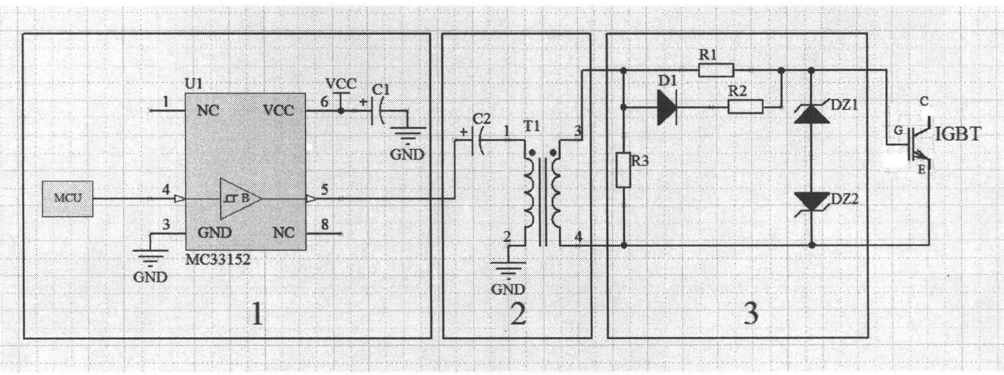
[0010] A novel IGBT drive circuit for high-frequency and high-voltage switching power supplies of the present invention is shown in Figure 1, comprising a switch control circuit (1), a pulse transformer isolation circuit (2) and a voltage stabilizing circuit (3); the front-end controller MCU generates the IGBT The driving signal is input to the high-speed dual-channel non-inverting driver MC33152; the output terminal is connected to the primary circuit of the pulse transformer isolation circuit, which is isolated and transmitted to the secondary circuit through the pulse transformer isolation circuit; the output of the pulse transformer secondary circuit is connected to the input terminal of the voltage stabilizing circuit, The output terminals of the voltage stabilizing circuit are respectively connected to the gate and emitter of the IGBT.

[0011] In this embodiment, the above-mentioned switch control circuit (1) is composed of front-end controller MCU, power supply VCC, cap...


PUM


Abstract

The invention relates to an IGBT (Insulated Gate Bipolar Translator) driving circuit for a novel high-frequency high-voltage switching power supply, comprising a switching control circuit (1), a pulse transformer isolating circuit (2) and a voltage stabilizing circuit (3); a front controller MCU (Microprogrammed Control Unit) generates an IGBT driving signal and inputs into a high-speed two-circuit in-phase driver MC33152; an output end is connected with a primary circuit of the pulse transformer isolating circuit, and is isolated by the pulse transformer isolating circuit and transmitted to a secondary circuit; the output of the secondary circuit of the pulse transformer is connected with the input end of the voltage stabilizing circuit, and the output end of the voltage stabilizing circuit is respectively connected with the gate and emitter of the IGBT. The invention has the following characteristics of small voltage fluctuation of an input stage, quick switching response, low power consumption of switching on and off and complete isolation between the input stage and the gate, and a series resistor in the voltage stabilizing circuit can effectively inhibit high-frequency parasitic oscillation, thus effectively reducing the mutual interference between the driving circuit and the IGBT, improving the accuracy of the IGBT driving signal, and ensuring more reliable, safe and accurate driving control of the IGBT.

Description

1: Technical field [0001] The invention relates to an IGBT driving circuit for a switching power supply, in particular to an IGBT driving circuit for a high-frequency and high-voltage switching power supply for a high-power electrostatic precipitator. 2: Background technology [0002] With the expansion of human production scale, air pollution tends to be serious. Dust is one of the main pollutants that cause air pollution. Industries such as coal processing, mining, electric power, metallurgy, oil refining, chemical industry, and papermaking are all sources of dust emissions. Electrostatic precipitators can effectively reduce dust emissions in industrial production, and the recovered dust contains a large amount of precious materials such as metals, thereby effectively reducing the loss of a large amount of precious metal materials. At present, most of the electrostatic precipitators used in my country are powered by industrial frequency power supplies, which have obvious ...

Claims


Application Information

Patent Timeline
IPC IPC(8): H02M1/06
Inventor 张潮海李金华
Owner CHANGSHU YINGNA ENERGY TECH
Learn More