Fast triggering system of resonant current limiter thyristor valve and working method of fast triggering system

A technology of thyristor valve and current limiter, which is applied in the field of power system, can solve the problem that the current limiter cannot meet the working speed of the system, and achieves the effect of good quickness and sensitivity and ensuring safety.

Inactive Publication Date: 2012-02-15
SHANGHAI UNIVERSITY OF ELECTRIC POWER
View PDF3 Cites 10 Cited by
  • Summary
  • Abstract
  • Description
  • Claims
  • Application Information

AI Technical Summary

Problems solved by technology

[0006] The invention aims at the problem that the operating speed of the current limiter cannot satisfy the system, and proposes a fast trigger system and working method for the thyristor valve of the resonant current limiter, which has good quickness and reliability

Method used


Image

  • Fast triggering system of resonant current limiter thyristor valve and working method of fast triggering system
  • Fast triggering system of resonant current limiter thyristor valve and working method of fast triggering system
  • Fast triggering system of resonant current limiter thyristor valve and working method of fast triggering system

Examples


Embodiment Construction

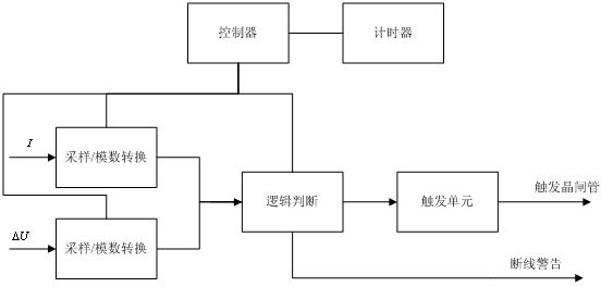
[0019] The fault signal of the current limiter body refers to the short circuit current signal, the resonant capacitor voltage signal and the current limiting reactance voltage signal. The main body fault signal enters the identification unit module after being adopted by the sensor. The identification module adopts the fast identification method of resonance voltage difference. After the identification method judges the short-circuit fault, it sends a criterion signal to the photoelectric trigger and monitoring unit, and the trigger unit sends a trigger signal to the thyristor electronic board TE, and the TE board sends a trigger signal to the thyristor to make the thyristor operate, such as figure 1 The schematic diagram of the system is shown.

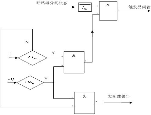
[0020] In the steady state, due to the power frequency resonance of the current-limiting element, the current-limiting reactance voltage and the resonant capacitor voltage have the same amplitude and opposite directions, so the dif...


PUM


Abstract

The invention relates to a fast triggering system of a resonant current limiter thyristor valve and a working method of the fast triggering system. The system mainly comprises a sampling module, a controller, a clock circuit, a triggering unit and an alarm circuit, wherein the sampling module is used for sampling line current and resonance voltage difference signal at high speed; the clock circuit is used for providing an overall clock signal and providing a reference time for the system; and the controller is used for realizing a fault recognition logic matching scheme by adopting a field programmable technology and converting a criteria signal into a thyristor valve triggering signal. A model experiment indicates that the resonance voltage difference recognition method can provide a criteria output signal within 1ms. The fast triggering system disclosed by the invention has the advantages of fast recognizing short-circuit fault and avoiding faults, such as switch reclosing, system disconnection, and the like.

Description

technical field [0001] The invention relates to the field of power systems, in particular to a fast trigger system and working method for a resonant current limiter thyristor valve. Background technique [0002] The excessive short-circuit current of the heavy load center has become an important factor restricting the development of the power grid. The series resonant current limiter has become a practical current limiter for 500kV ultra-high voltage power grid due to its simple principle, safety, reliability, and economical rationality. The principle of the series resonant current limiter is as follows: the current-limiting reactance is connected in series with a capacitor resonant with the power frequency; when a short-circuit fault occurs, the capacitor is quickly bypassed, which is equivalent to the input of the current-limiting reactance. The key to realize the active current limiting function of the current limiter is the fast bypass of the capacitor. The action spee...

Claims


Application Information

Patent Timeline
IPC IPC(8): H02H9/02G05B19/04
Inventor 王华昕张小宝赵永熹
Owner SHANGHAI UNIVERSITY OF ELECTRIC POWER
Why Eureka
Try Eureka