
Method and device for current compensation to current transformer winding of leakage protection device

A technology of leakage protection device and current transformer, applied in emergency protection circuit devices, emergency protection devices with automatic disconnection, circuit devices, etc., can solve the influence of power supply reliability, high safety pressure on electricity consumption, and difficulty in finding fault points and other problems to achieve the effect of ensuring reliable power supply and ensuring electricity safety

Inactive Publication Date: 2012-02-15
谭昆玲
View PDF5 Cites 7 Cited by
  • Summary
  • Abstract
  • Description
  • Claims
  • Application Information

AI Technical Summary

Problems solved by technology

Due to various reasons, leakage protectors often or even frequently malfunction, causing power supply interruptions and seriously affecting the reliability of power supply
There are several situations where this contradiction will occur: 1. The inherent capacitive leakage current of the power line will cause the leakage protector to operate, such as the electric heating floor heating facility and the ground electric heating moisture removal facility, because the phase line is close to the ground The line is long and flat, which will generate capacitive leakage, which will cause the leakage protector to operate, but this leakage is normal and inevitable, and the leakage protector cannot be shut down because of abnormal operation; 2. Some office buildings have important For data equipment, in order to resist the voltage and current surge interference in the power grid, a large-capacity capacitor is installed on the power consumption side. Once it is put into operation, the capacitor will generate capacitive leakage current to the ground and cause the leakage protector to operate. The solution is Using an isolation transformer
Although this solves the reliability of the power supply, it does not take safety into account and increases the cost; 3. Internet cafes or office buildings with multiple computers, because each computer has a normal leakage current of about 5 mA when it is working normally , the number of computers is too many, it will also cause the leakage protector to operate, and the leakage current will change with the season and air humidity
4. For the existing power supply system that has been laid, due to the wet ground, aging insulation or partial damage, the resistive leakage current increases, causing the leakage protector to operate abnormally or frequently, and in severe cases, the gate cannot be closed.
Although there is leakage in the line, it does not affect the normal use of the power supply system, and it is difficult to find the fault point
Let the leakage protector out of operation, and there is a problem of electricity safety
5. The problem of frequent action of leakage protectors at the construction site
The environment of the construction site is harsh, with various dust and moisture, which causes the residual current protection to operate frequently, which annoys the electrical engineers on site. On the one hand, power supply is required due to the construction period, and on the other hand, there is a lot of pressure on electricity safety.
6. In the rural power supply network, a large number of leakage protectors are installed. Due to the long power supply lines, low technical level of personnel, and poor equipment performance, the leakage protectors often operate and the power supply is interrupted.
1. Under normal capacitive leakage conditions, the leakage protector can not only ensure high sensitivity to protect, but also ensure the reliability of power supply, instead of relying on increasing the operating current of leakage protection to ensure reliable power supply and increase personal electric shock risk
2. Under normal resistive leakage conditions, the leakage protector can not only ensure high sensitivity to protect, but also ensure the reliability of power supply, instead of relying on increasing the operating current of leakage protection to ensure reliable power supply and increase personal electric shock risk

Method used


Image

  • Method and device for current compensation to current transformer winding of leakage protection device
  • Method and device for current compensation to current transformer winding of leakage protection device
  • Method and device for current compensation to current transformer winding of leakage protection device

Examples


Embodiment Construction

[0017] The present invention will be further described below in conjunction with the accompanying drawings and embodiments, but the present invention is not limited in any way, and any transformation made based on the teaching of the present invention falls within the protection scope of the present invention.

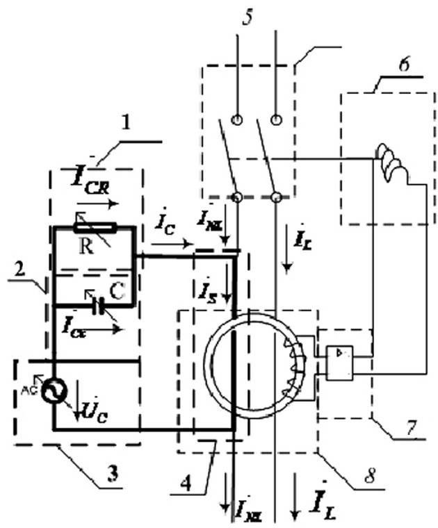
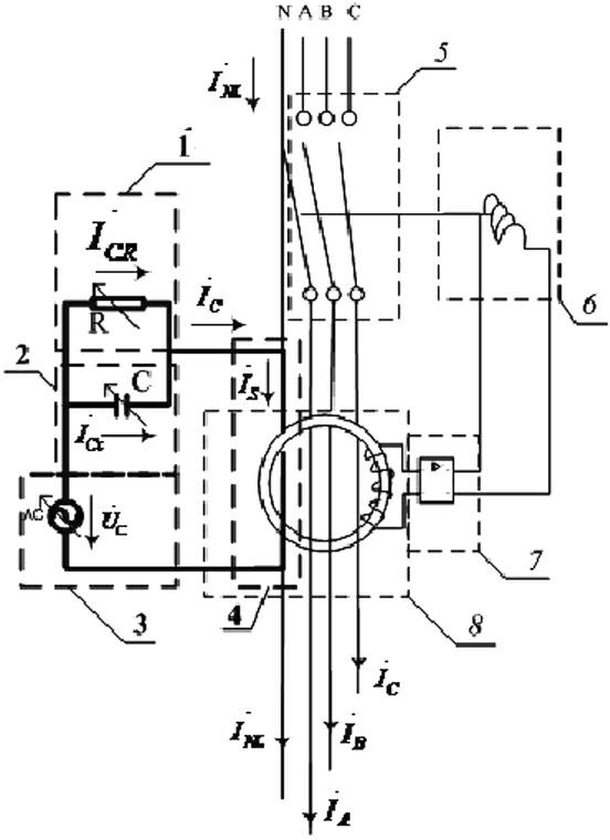
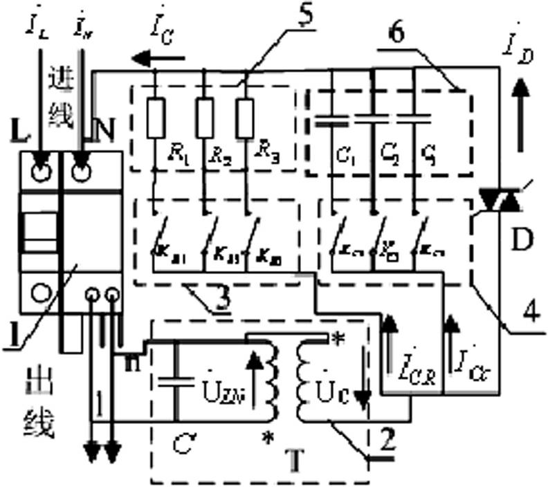
[0018] Such as Figure 1~2 As shown, the method of the present invention includes providing the resistor branch 1 of the resistive compensation current, the capacitor branch 2 of the capacitive compensation current, the compensation power supply 3 of the compensation current Ic, passing through the leakage protector with a current transformer magnetic The primary winding 4 of the core; the size of the compensation current Ic can be realized by adjusting the resistor branch 1 and the capacitor branch 2, or by adjusting the voltage value of the compensation power supply 3.

[0019] The adjustment of the resistor branch 1, the capacitor branch 2 or the compensation po...


PUM


Abstract

The invention discloses a method and a device for current compensation to the current transformer winding of a leakage protection device. The device comprises a resistor branch circuit which is used for providing resistive compensating current, a capacitor branch circuit which is used for providing capacitive compensating current, a compensating power supply which is used for providing compensating current Ic and a primary winding which penetrates through the magnetic core of a current transformer for a leakage protector. The magnitude of the compensating current Ic can be adjusted through the adjustment of the resistor branch circuit and the capacitor branch circuit or the adjustment of the voltage value of the compensating power supply. Normal leakage current and accidental fault leakage current in an electricity-consuming system are distinguished through the closing times of an air switch with the leakage protector and the magnitude of the relevant compensating current value. Under the situation of normal leakage, the current is balanced through the compensating current to ensure reliable power supply; and under the situation of accidental leakage, the leakage protector acts to cut off the power supply to ensure electrical safety. The contradiction between the power supply reliability and the electrical safety caused by the leakage protector used in the neutral point grounding system of the existing power transformer is overcome.

Description

technical field [0001] The invention belongs to the technical field of leakage protection, and in particular relates to a current to the leakage protection device which can overcome the technical defects of the second and third level leakage protectors in the three-level protection system of the neutral point grounding system of the existing power transformer. A method and device for compensating current in transformer windings. Background technique [0002] In the power transformer neutral point grounding system, at the beginning of the design of the leakage protector (also called the residual current protector), based on the fact that the resistive and capacitive leakage current on the phase line of the power line is smaller than its operating current, it will cause a certain delay in the action of the protector. is the fault leakage current. But in fact, the normal leakage current on the phase line, or the leakage current that can maintain the normal operation of the pow...

Claims


Application Information

Patent Timeline
IPC IPC(8): H02H3/32
Inventor 谭昆玲邹守宝
Owner 谭昆玲
Learn More