
Railway side slope crag rockfall monitoring and warning system based on fiber grating sensing technology

A fiber grating and alarm system technology, applied to alarms, instruments, etc., can solve the problems of anti-electromagnetic interference of monitoring signals, inability to actively warn and monitor, and inability to continue normal work, so as to reduce false alarms, ensure train operation safety, and use Safe and reliable effect

Active Publication Date: 2012-02-15
WUHAN WUTOS
View PDF3 Cites 40 Cited by
  • Summary
  • Abstract
  • Description
  • Claims
  • Application Information

AI Technical Summary

Problems solved by technology

[0009] The technical problem to be solved by the present invention is to provide a monitoring and alarm system for dangerous rockfall on railway slopes based on optical fiber grating sensing technology. In view of the problems existing in the existing monitoring technology for rockfall on railway slopes, the present invention can solve the following key technical problems : Solve the problem that the existing railway slope rockfall monitoring and alarm system can only perform alarm monitoring passively but cannot actively warn and monitor; solve the problem that the existing railway slope rockfall monitoring system monitoring electrical sensors cannot continue to work normally in severe weather Problem; Solve the problem of anti-electromagnetic interference and long-distance transmission of the monitoring signal of the existing railway slope monitoring system; Solve the problem of easy missing and high false alarm rate under the single monitoring method of the railway slope monitoring system

Method used


Image

  • Railway side slope crag rockfall monitoring and warning system based on fiber grating sensing technology
  • Railway side slope crag rockfall monitoring and warning system based on fiber grating sensing technology
  • Railway side slope crag rockfall monitoring and warning system based on fiber grating sensing technology

Examples


Embodiment

[0042] 1. Rock mass deformation and loosening monitoring subsystem based on fiber grating smart bolt

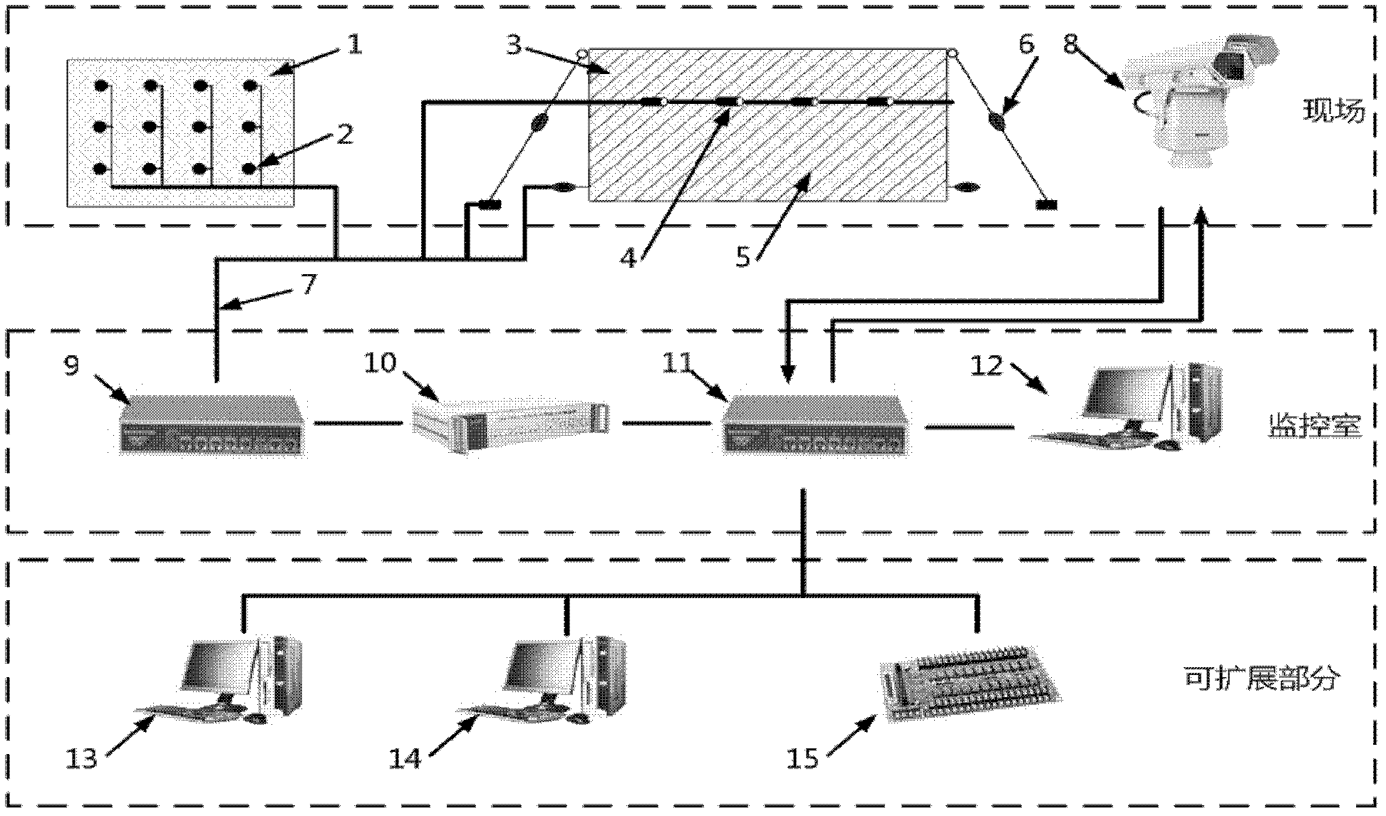
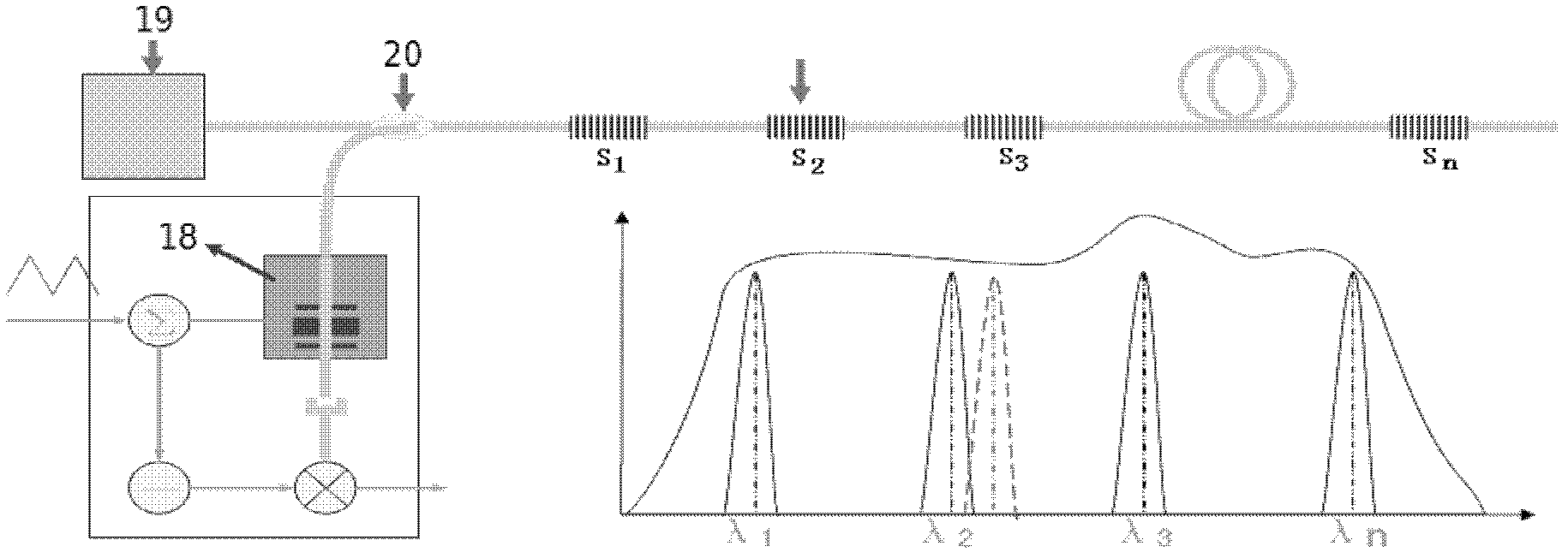
[0043] The deformation and loosening of the weathered rock mass will seriously endanger the safety of railway traffic. In order to monitor the deformation and loosening state of the rock mass after reinforcement. Based on the principle of optical fiber sensing, this subsystem has developed a fiber grating intelligent anchor, which penetrates into the weathered rock area of ​​the active network slope protection surface of the slope, and can monitor the distribution and development of the force along the axial direction of the anchor. Monitoring of the force situation of the weathered rock formation in the block area. figure 2 It is the structural diagram of the fiber grating intelligent anchor rod. The length of the anchor rod is determined according to the monitoring site geological survey, and steel bars or steel cables can be used.

[0044] For a single anchor, the impor...


PUM


Abstract

The invention provides a railway side slope crag rockfall monitoring and warning system based on a fiber grating sensing technology. The system provided by the invention comprises on-site monitoring equipment and monitoring control equipment. wherein the on-site monitoring equipment is used for monitoring the rock mass deformation and looseness of an active network protection zone of a railway line side slope and monitoring crag rockfall by using as flexible passive network as a monitoring carrier; the monitoring control equipment is connected with the on-site monitoring equipment; the on-site monitoring equipment comprises a rock mass deformation and looseness monitoring subsystem, a rockfall broken network monitoring and warning subsystem and a rockfall state monitoring subsystem which are connected with the monitoring control equipment; and the monitoring control equipment comprises a fiber terminal box (9), a fiber grating signal demodulator (10), a network switch (11) and a computer system (12) which are sequentially connected. According to the invention, the accuracy of a railway crag rockfall warning and monitoring technology is enhanced and the train transport operation safety is better guaranteed.

Description

technical field [0001] The invention is a monitoring and alarming system applicable to dangerous rockfall on railway slopes, and belongs to the technical fields of optical fiber sensing technology, computer system integration technology, signal detection technology and railway disaster prevention safety monitoring technology. Background technique [0002] my country is a big country with railways. In recent years, railway technology has developed rapidly. The mileage of passenger trains is getting longer and longer. The speed of trains is getting faster and faster. The requirements for driving safety are getting higher and higher. The automatic monitoring and Early warning technology is getting more and more attention. Railway construction on the "Interim Regulations on the Design of Newly-built 300-350 km / h Passenger Dedicated Line Railways" clearly stipulates that: passenger dedicated line railways need to be equipped with disaster prevention and safety monitoring systems, ...

Claims


Application Information

Patent Timeline
IPC IPC(8): G08B21/10
Inventor 胡军黄辛袁良峰尹达刘简印新达
Owner WUHAN WUTOS
Learn More