Device and measuring method for measuring magnetoconstriction coefficient through multi-beam laser heterodyne secondary harmonic method

A technology of magnetostriction coefficient and laser heterodyne, applied in magnetostrictive performance measurement, magnetic performance measurement, etc., can solve the problems of slow signal processing operation speed, low measurement accuracy, and poor acquisition effect of laser difference frequency signals

Inactive Publication Date: 2012-02-15
HARBIN INST OF TECH
View PDF6 Cites 12 Cited by
  • Summary
  • Abstract
  • Description
  • Claims
  • Application Information

AI Technical Summary

Problems solved by technology

[0007] The present invention provides a multi-beam laser in order to solve the problem of low measurement accuracy caused by poor acquisition effect of laser difference frequency signal and slow operation speed of signal processing in the existing method of measuring magnetostriction coefficient by multi-beam laser heterodyne. Device and method for measuring magnetostriction coefficient with heterodyne second harmonic

Method used


Image

  • Device and measuring method for measuring magnetoconstriction coefficient through multi-beam laser heterodyne secondary harmonic method
  • Device and measuring method for measuring magnetoconstriction coefficient through multi-beam laser heterodyne secondary harmonic method
  • Device and measuring method for measuring magnetoconstriction coefficient through multi-beam laser heterodyne secondary harmonic method

Examples


specific Embodiment approach 1

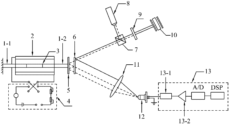
[0062] Specific implementation mode 1. Combination figure 1 Illustrate this specific embodiment, the device of multi-beam laser heterodyne second harmonic measurement magnetostriction coefficient, it comprises the first fixed rod 1-1, the second fixed rod 1-2, excitation coil 2, iron-nickel alloy to be measured Sample 3, DC stabilized power supply 4, plane mirror 5, thin glass plate regardless of thickness 6, polarizing beam splitter PBS7, H0 solid-state laser 8, quarter-wave plate 9, vibrating mirror 10, converging lens 11, photoelectric detection device 12 and signal processing system 13,

[0063] The DC stabilized power supply 4 is used to provide working power for the excitation coil 2, the iron-nickel alloy sample 3 to be tested is placed in the center of the excitation coil 2, and one end of the iron-nickel alloy sample 3 to be tested is fixedly connected to one end of the first fixed rod 1-1 , the other end of the first fixed rod 1-1 is fixedly arranged, the other end ...

specific Embodiment approach 2

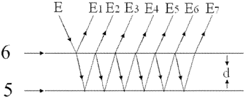
[0067] Embodiment 2. The difference between this embodiment and the device for measuring magnetostriction coefficient by multi-beam laser heterodyne second harmonic described in Embodiment 1 is that the distance d is 20 mm, which can be set arbitrarily according to needs.

specific Embodiment approach 3

[0068] Embodiment 3. The difference between this embodiment and the device for measuring the magnetostriction coefficient by multi-beam laser heterodyne second harmonic described in Embodiment 1 or 2 is that the first fixed rod 1-1 and the second fixed rod 1-1 Both end faces of the rod 1-2 are glued with non-magnetic materials.


PUM


Abstract

The invention discloses a method for measuring a magnetoconstriction coefficient through a multi-beam laser heterodyne secondary harmonic method, which relate to the methods for measuring the magnetoconstriction coefficient. By using the device and the measuring method, the problem that a conventional method for measuring the magnetoconstriction coefficient by adopting a multi-beam laser heterodyne method has lower measurement precision. According to the device and the measuring method, through introducing a polarizer into a light path, light signals which are incident at different moments are added with a light frequency, so that the reflected light passing through the front surface of a thin glass plate and the light which is reflected for many times by a plane reflecting mirror generate multi-beam heterodyne secondary harmonic signals under the condition that the interference is met, and the information to be measured is successfully modulated in the frequency difference of medium-frequency heterodyne secondary harmonic signals, so as to achieve the measurement of the magnetoconstriction coefficient. The device and the measuring method are applicable to the measurement of the magnetoconstriction coefficient.

Description

technical field [0001] The invention relates to a device and a measuring method for measuring the magnetostriction coefficient. Background technique [0002] The magnetic domains of ferromagnets will be aligned under the action of an external magnetic field, thereby causing changes in the lattice spacing in the medium, resulting in changes in the length of ferromagnets, which is called the magnetostrictive effect. Since this phenomenon was first discovered by Joule in 1842, it is also called the Joule effect. Magnetostriction not only has an important influence on the magnetism of materials (especially on the initial permeability, coercive force, etc.), but also the effect itself is widely used in practice, such as: magnetostriction technology can be used in mechanical Vibration and ultrasonic transducers have important applications in lidar and other aspects. [0003] Ultrasonic generators and receivers can be made by using the length change of materials under the action ...

Claims


Application Information

Patent Timeline
Patent Type & Authority Applications(China)
IPC IPC(8): G01R33/18
Inventor 李彦超王春晖高龙曲杨张峰
Owner HARBIN INST OF TECH
Why Eureka
Try Eureka