Movable oxygenation device

An oxygen-enhancing device and a mobile technology, applied in the field of mobile oxygen-enhancing devices, can solve the problems of poor pile fixation effect, noise, limited effective oxygen-enhancing range, etc., and achieve the effect of strong oxygen-enhancing ability and easy deceleration.

Inactive Publication Date: 2012-02-15
郑成忠
View PDF5 Cites 6 Cited by
  • Summary
  • Abstract
  • Description
  • Claims
  • Application Information

AI Technical Summary

Problems solved by technology

Water surface oxygenation usually uses the stirring of the impeller located on the water surface to dissolve the oxygen in the air into the water, because it is difficult to achieve the effect of oxygenated water spreading to the bottom of the water area, and compared with the underwater oxygenation method, it has large noise and vibration The defects are being gradually replaced by underwater aeration devices
A typical underwater aeration device, such as the "one-way jet type mobile aeration device" disclosed in the patent No. 02272633.0 and the publication number CN2561217, includes a submersible motor connected to the air-water mixing chamber of the submersible motor. The suction pipe, the floating body device arranged on the suction pipe, one end of the submersible motor has a power transmission shaft connected coaxially with the installation sleeve of the spiral suction blade through the air chamber, and the outer edge of the spiral suction blade is connected with the installation of the spiral water blade The inner wall of the wheel shell is fixed, and the floating device is composed of multiple floating drums. This technical scheme makes the underwater strip-shaped rotating air flow and strip-shaped rotating water flow fully mixed, and generates swirling flow in the fish pond, increasing the The oxygenation effect of the fish pond, but due to the large drainage, it needs to be fixed in the fish pond when using it. The thick mud layer at the bottom of the fish pond makes the fixing effect of the pile poor, and the user needs to use something like nylon rope Bundled, and because the position is fixed, there is only one jet direction, the effective range of oxygenation is limited, and several mobile oxygenation devices need to be added in different directions

Method used


Image

  • Movable oxygenation device
  • Movable oxygenation device
  • Movable oxygenation device

Examples


no. 1 example

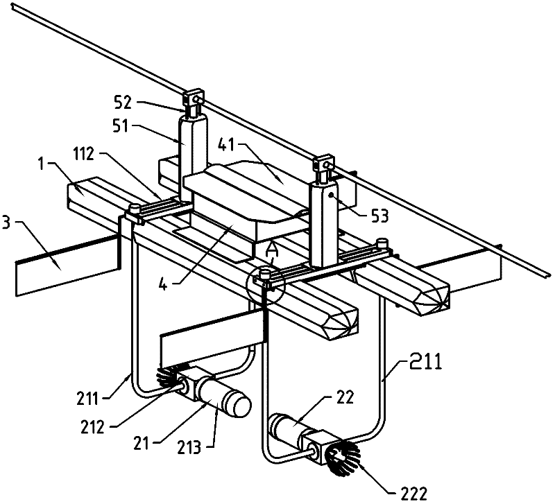
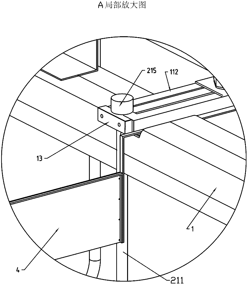
[0038] see figure 1, the mobile aeration device is provided with a pair of buoys 1 arranged symmetrically along the center line. The buoyancy provided by the buoys 1 should meet the requirement of floating at a fixed depth when carrying the full weight of the mobile aeration device, that is, it can float on the water surface or Floating underwater, the buoyancy produced by the pair of buoys 1 of the present embodiment is designed to be greater than the gravity suffered by the entire device. The two buoys 1 are fixedly connected by a pair of beams 112 . In other feasible implementation manners, the buoy 1 can also be a boat-shaped shell, and the inside of the shell can be hollow, or can be filled with materials such as foam that can provide sufficient buoyancy.

[0039] The first air-water mixer 21 is used to propel the buoy 1 forward, and it is arranged below the centerline of the buoy 1 . The second air-water mixer 22 is used to push the buoy 1 back, and it is arranged belo...

no. 2 example

[0052] see Figure 5 , on the basis of the first embodiment, this embodiment adds a third air-water mixer 23, which is used to increase oxygen to the port side waters, which is arranged below the port side; a fourth air-water mixer 24, which is used to add oxygen to the starboard waters Oxygenation, which is located below the starboard side. The third air-water mixer 23 and the fourth air-water mixer 24 can work simultaneously or stop working simultaneously according to the specific conditions of the route. The third air-water mixer 23 and the fourth air-water mixer 24 are also fixed on the buoy 1 through brackets that can be moved up and down relative to the buoy 1 . The bracket includes a pipe body as the suction pipe of the third air-water mixer 23 and the fourth air-water mixer 24 . Its installation method that can move up and down is the same as that of the first embodiment. When needing to expand the range of oxygenation radiation to both sides of guide wire 6, start ...

no. 3 example

[0055] see Figure 7 , on the basis of the second embodiment, this embodiment adds a feed throwing device 7, and the throwing device 7 has a throwing port on the left side and a starboard side respectively, and the other parts form a watertight box, but there is an open and close feeding cover , for adding feed. The relatively small control box 4 is arranged before and / or behind the feed spreading device 7 .

[0056] see Figure 8 , the feed throwing device 7 is mainly composed of a motor, a transmission system, and a pair of centrifugal rotating disks 73 and a hopper 71, which are installed on the buoy, and the upper surface of the centrifugal disk 73 is provided with ribs 72 in the radial direction, and the motor drives the centrifugal rotating disk through the transmission system. 73 rotates at a high speed, and the feed particles falling from the hopper 71 are thrown toward the port side and the starboard side along the direction having an elevation angle with the horizo...


PUM


Abstract

The invention discloses a movable oxygenation device which comprises a floating body, a first gas-water mixer and a second gas-water mixer, wherein the floating body is provided with a buoyancy force for floating at the fixed depth when the floating body is used for bearing total weight of the movable oxygenation device and is provided with a midline, fore and aft, a port and a starboard; the first gas-water mixer is used for pushing the floating body to move forwards and is arranged below the midline of the floating body; the air suction end of an air suction tube of the first gas-water mixer is led to the upper part of the floating body; the second gas-water mixer is used for pushing the floating body to retreat and is arranged below the midline of the floating body; the air suction endof an air suction tube of the second gas-water mixer is led to the upper part of the floating body; and the first gas-water mixer and the second gas-water mixer are respectively arranged at the ends near to the fore and the aft and select to work together. The movable oxygenation device is suitable for oxygenating a pond for cultivation.

Description

technical field [0001] The invention relates to special equipment for aquaculture, in particular to a mobile aeration device. Background technique [0002] Existing fishpond oxygenation devices are divided into two types: water surface oxygenation and underwater oxygenation according to the way they give oxygen to aquaculture waters. Water surface oxygenation usually uses the stirring of the impeller located on the water surface to dissolve the oxygen in the air into the water, because it is difficult to achieve the effect of oxygenated water spreading to the bottom of the water area, and compared with the underwater oxygenation method, it has large noise and vibration The defects are gradually being replaced by underwater aeration devices. A typical underwater aeration device, such as the "one-way jet type mobile aeration device" disclosed in the patent No. 02272633.0 and the publication number CN2561217, includes a submersible motor connected to the air-water mixing chamb...

Claims


Application Information

Patent Timeline
Patent Type & Authority Applications(China)
IPC IPC(8): A01K61/00
CPCY02A40/81
Inventor 郑成忠
Owner 郑成忠
Why Eureka
Try Eureka