Eureka AIR delivers breakthrough ideas for toughest innovation challenges, trusted by R&D personnel around the world.

Fixture for vertical LED (light emitting diode) lead frame

A lead frame and vertical technology, which is applied in the field of fixtures for vertical LED lead frames, can solve problems such as increasing costs, achieve the effects of reducing demand, reducing production costs, and simple operation

Inactive Publication Date: 2012-02-08
THE 45TH RES INST OF CETC
View PDF3 Cites 5 Cited by
  • Summary
  • Abstract
  • Description
  • Claims
  • Application Information

AI Technical Summary

Problems solved by technology

[0002] As a new type of light source, LED lighting has the remarkable characteristics of green environmental protection, high efficiency and energy saving. In recent years, the scope of use in various fields has become wider and wider. , LED lighting source, etc.) The shape is also constantly changing. Pasting the chip on the LED lead frame is the core process of producing LED products. This puts forward higher requirements for the key equipment in the production process of LED products. To adapt to more and more different types of products, currently in the production process of LED products, different products usually need to be clamped with different LED lead frame fixtures, which requires different fixtures for different products for manufacturers , thereby increasing the cost of production

Method used


Image

  • Fixture for vertical LED (light emitting diode) lead frame
  • Fixture for vertical LED (light emitting diode) lead frame
  • Fixture for vertical LED (light emitting diode) lead frame

Examples


Embodiment Construction

[0016] Below in conjunction with accompanying drawing, the present invention is described in further detail:

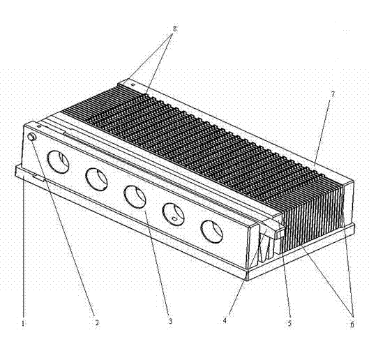
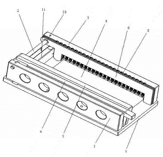
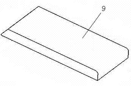
[0017] as attached figure 1 , 2 , 3, 4, and 5, the present invention includes a base plate 1, a positioning block 11, a backing plate 9, a guide shaft 2, a compression strip 4, a pressure plate 5, a clip 6, a wave gasket 10, and left and right side plates 3, 7, one end of the positioning block 11 is fixed on the base plate 1, the positioning block 11 is a cuboid, the backing plate 9 is fixed on one side of the positioning block 11 on the bottom plate 1, the backing plate 9 is a cuboid, the left The side plate 3 and the right side plate 7 are fixed on the upper part of both sides of the bottom plate 1, the guide shaft 2 is fixed between the upper end of the left side plate 3 and the right side plate 7, and the pressing strip 4 and the pressing plate adjacent to the left side plate in turn 5 and one end of the clip 6 are fitted on the guide shaft 2 through the pin hol...


PUM


Abstract

The invention relates to a fixture for a vertical LED (light emitting diode) lead frame. The fixture comprises a bottom plate, a positioning block, a backing plate, a guiding axle, a compressing strip, a press plate, clamping pieces, a corrugated gasket, a left side plate and a right side plate, wherein the positioning block is fixed at one end of the bottom plate, the backing plate is fixed on one side of the positioning block, the left and right side plates are fixed at the upper parts of two sides of the bottom plate, and the guiding axle is fixed between the upper end parts of the left and right side plates; one ends of the compressing strip, the press plate and the clamping piece are sleeved on the guiding axle through pin holes on the one ends; the corrugated gasket is arranged between the adjacent two clamping pieces; and the vertical LED lead frame is arranged between the clamping pieces. The fixture provided by the invention has simplicity of operation and reliability of clamping and positioning, and the fixture can be adapted to vertical LED lead frames of different heights by only replacing the backing plate, thereby greatly reducing the quantity of types of fixture required by enterprises, lowering the production cost of enterprises and raising the labor productivity.

Description

technical field [0001] The invention relates to a fixture for a vertical LED lead frame, in particular to the technical field of semiconductors. Background technique [0002] As a new type of light source, LED lighting has the remarkable characteristics of green environmental protection, high efficiency and energy saving. In recent years, the scope of use in various fields has become wider and wider. , LED lighting source, etc.) The shape is also constantly changing. Pasting the chip on the LED lead frame is the core process of producing LED products, which puts forward higher requirements for the key equipment in the production process of LED products. Adapt to more and more different types of products. At present, in the production process of LED products, different products usually need to be clamped with different LED lead frame fixtures. For manufacturers, different fixtures need to be prepared for different products. , thus increasing the production cost of the enterp...

Claims


Application Information

Patent Timeline
Patent Type & Authority Applications(China)
IPC IPC(8): H01L33/00H01L21/683B25B11/00
Inventor 郎平任绍彬郭东郝靖周启舟
Owner THE 45TH RES INST OF CETC
Why Eureka
Eureka Blog
Learn More