Method for testing the horizontal displacement of CRTS-II type plate ballastless rail bridge abutment of high-speed railway

A slab ballastless track, CRTS-II technology, applied in the direction of measuring devices, instruments, etc., can solve the problems of difficult automatic monitoring, large error of test value, large test error, etc., to avoid bending deformation and large frictional resistance, bridge The horizontal displacement value of the table is accurate and the effect of improving the test accuracy

Inactive Publication Date: 2013-06-12
SOUTHWEST JIAOTONG UNIV
View PDF3 Cites 0 Cited by
  • Summary
  • Abstract
  • Description
  • Claims
  • Application Information

AI Technical Summary

Problems solved by technology

However, if the slender reference rod with a length of more than 50m is made of non-metallic materials such as concrete, it is easy to break and it is not easy to realize the test; while it is made of metal materials, the thermal expansion and contraction of the metal material is obvious, and such a long metal Rods are also prone to bending deformation, resulting in a large error in the final test value, and it is also impossible to accurately test the horizontal displacement of the abutment
[0004] The horizontal displacement of the bridge abutment can also be tested with an inclinometer. The principle is to measure the angle change between the axis of the inclinometer pipe buried in the bridge abutment and the stable soil layer of the foundation and the vertical line, so as to calculate the The horizontal displacement of the platform has a large test error, and the systematic error within the length range of the 30m inclinometer tube can reach 8mm, and the test accuracy cannot meet the requirements
When the inclinometer is used to test, it is necessary to manually work on site to complete the data collection, and it is not easy to realize automatic monitoring. Due to the special location and environment of many work sites, it brings great difficulties to displacement testing and data collection.

Method used


Image

  • Method for testing the horizontal displacement of CRTS-II type plate ballastless rail bridge abutment of high-speed railway
  • Method for testing the horizontal displacement of CRTS-II type plate ballastless rail bridge abutment of high-speed railway
  • Method for testing the horizontal displacement of CRTS-II type plate ballastless rail bridge abutment of high-speed railway

Examples


Embodiment

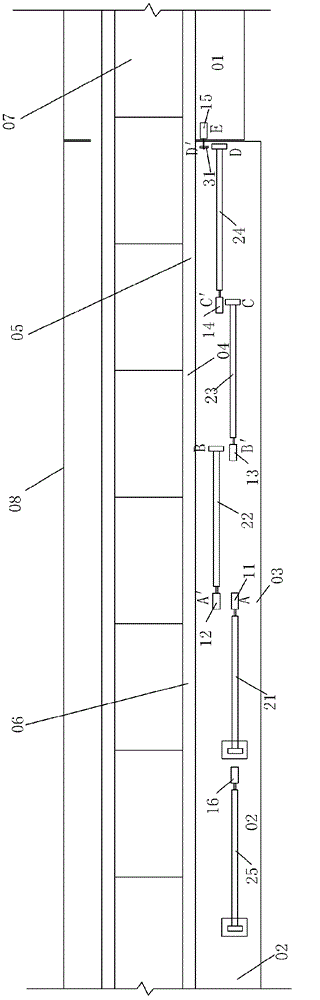
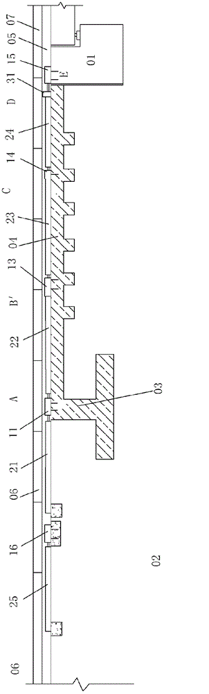
[0035] Figure 1-2 Shown, a kind of embodiment of the present invention is a kind of high-speed railway CRTS-II type slab type ballastless track abutment horizontal displacement testing method, and its steps are:

[0036] a. Test end thorn horizontal displacement

[0037] Fix the displacement sensor-11 on the test point A of the end thorn 03, the telescopic rod of the displacement sensor-11 is connected with the proximal end of the reference rod-21, and the far end of the reference rod-21 is anchored on the roadbed 02, and the displacement sensor-11 11 Obtain the horizontal displacement test value X of end thorn 03 0 ;

[0038] b. Test the horizontal deformation of the friction plate

[0039] Fix the displacement sensor 2 12 on the test point A' of the end thorn 03, the test point A' and the test point A of the end thorn 03 are located on the same cross-section, the telescopic rod of the displacement sensor 2 12 and the distal end of the reference rod 22 connection, the pr...


PUM


Abstract

The invention discloses a method for testing the horizontal displacement of a CRTS-II type plate ballastless rail bridge abutment of a high-speed railway. The method comprises the following steps of: a) testing the horizontal displacement of an end spine; b) testing the horizontal deformation of a friction plate; c) testing the horizontal displacement of the bridge abutment relative to the friction plate; d) testing a temperature correction value; and e) calculating the horizontal displacement of the bridge abutment. The test value of the temperature correction displacement sensor realizes correction of the test values of the displacement sensors connected with the end parts of reference rods on the end spine and the friction plate. The method has the advantages of clear principle, low measurement error and high accuracy, and meets the test of the horizontal displacement of the CRTS-II type plate ballastless rail bridge abutment of the high-speed railway.

Description

technical field [0001] The invention relates to a line engineering test method, in particular to a test method for the horizontal displacement of an abutment of a CRTS-II type slab ballastless track of a high-speed railway. Background technique [0002] High-speed railway CRTS-II (China Railway Track System) slab ballastless track uses high-quality embankment filler to form a transition section within tens of meters of the subgrade at the junction of the reinforced concrete abutment at the end of the bridge and the subgrade. A reinforced concrete friction plate with a length of 50-60m and a reinforced concrete end spike with a thickness of 1m cast in place at the far end of the friction plate are set on the subgrade surface inside. The reinforced concrete base of this kind of slab ballastless track on the bridge is not broken at the bridge joint at the beam end, but extends on the upper part of the reinforced concrete friction plate in the transition section, and is then int...

Claims


Application Information

Patent Timeline
Patent Type & Authority Patents(China)
IPC IPC(8): G01B21/02
Inventor 罗强张国发张良王冠肖双松魏永权陈坚陈虎刘钢吴兵
Owner SOUTHWEST JIAOTONG UNIV
Why Eureka
Try Eureka