
Structure and method for packaging blue-green laser chip based on thin crystal

A chip packaging structure, blue-green laser technology, applied in the laser field, can solve problems such as difficult operation, difficult actual production, and difficulty in deepening photoresist

Inactive Publication Date: 2012-02-01
NANJING CQ LASER TECH
View PDF4 Cites 3 Cited by
  • Summary
  • Abstract
  • Description
  • Claims
  • Application Information

AI Technical Summary

Problems solved by technology

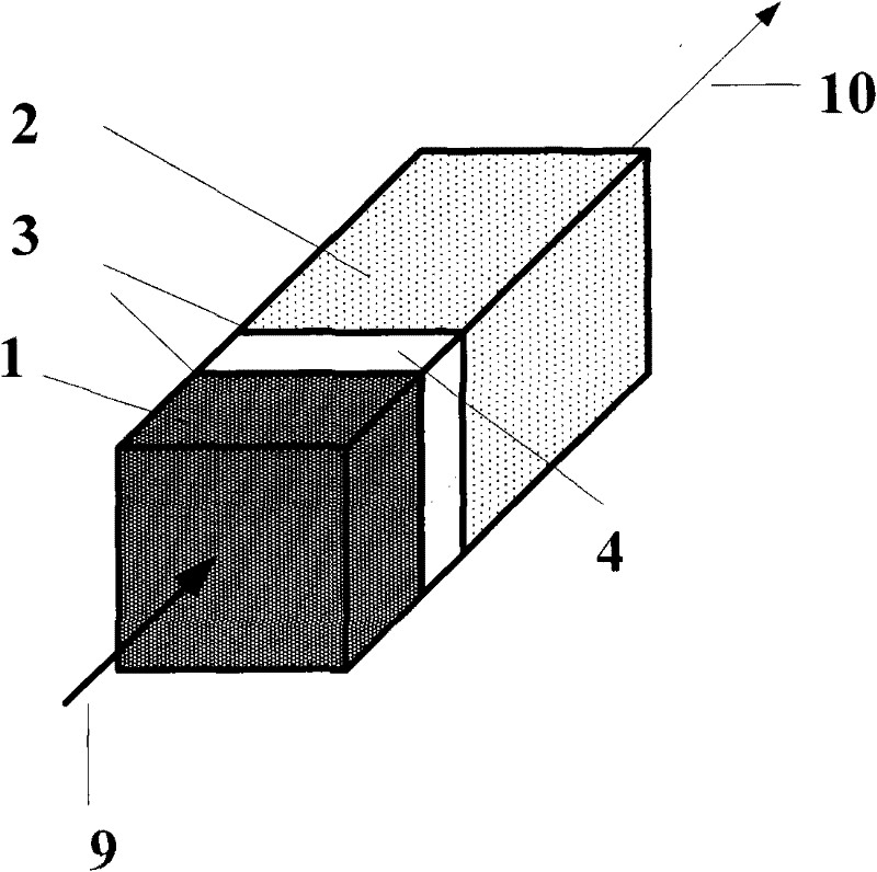
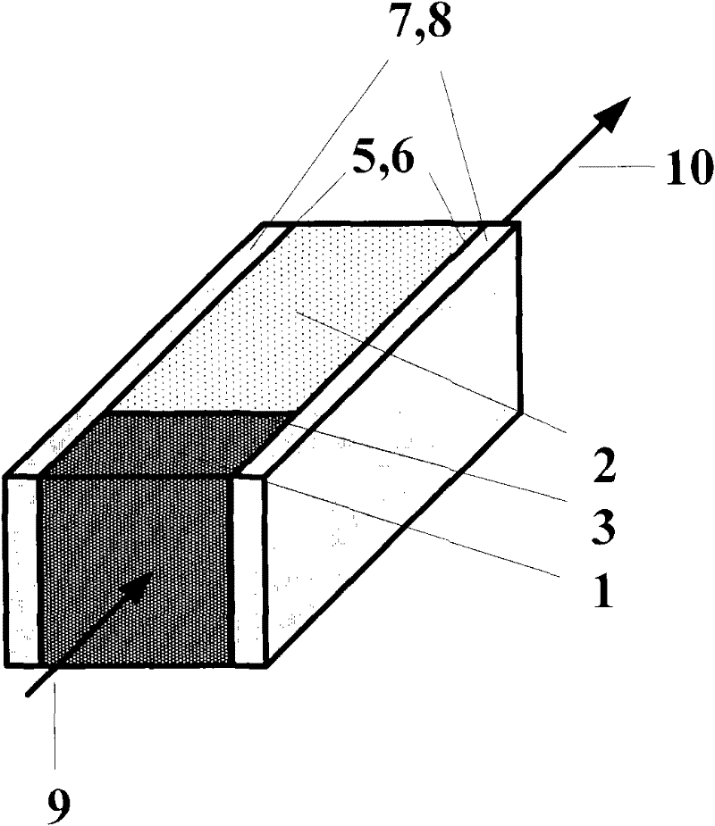
However, the size of the neodymium-doped working material 1 and the nonlinear frequency conversion crystal 2 in this chip structure is relatively large. If the size of the laser chip is further reduced, the effective area in the direction of light transmission will be reduced, that is, the cross-sectional area of ​​the light will be reduced. In actual packaging , there are the following difficulties in adopting this structure: one is that it is very difficult to deepen the light glue on the light-transmitting surface 3, and the other is that it is difficult to operate when the heat-conducting glue 5, 6 is used on both sides to bond the heat-conducting material silicon wafer 7, 8, and it is not easy for actual production

Method used


Image

  • Structure and method for packaging blue-green laser chip based on thin crystal
  • Structure and method for packaging blue-green laser chip based on thin crystal
  • Structure and method for packaging blue-green laser chip based on thin crystal

Examples


Embodiment 1

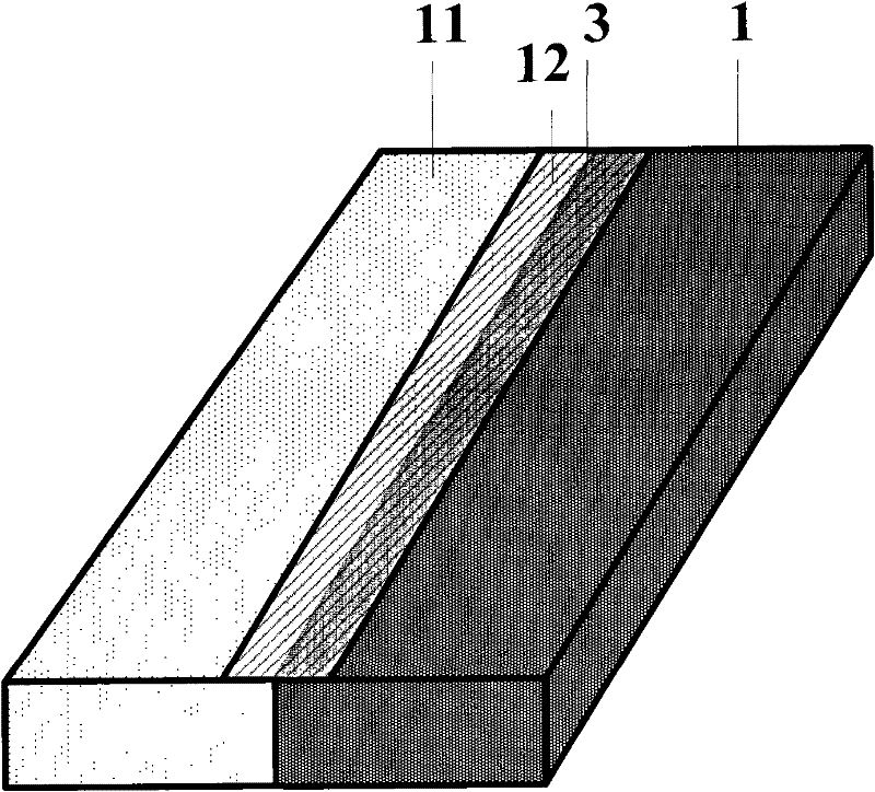
[0016] Embodiment one: structure such as Figure 2a , as shown in the figure b, the light-transmitting surface 3 of the thin neodymium-doped laser crystal 1 and the thin nonlinear frequency conversion crystal 11 is polished and cleaned, and then bonded by optical or optical glue. Then, use epoxy resin 12 to seal any side around the joint of the light-transmitting surface of the chip, a very small part of the epoxy-based resin penetrates into the joint of the light-transmitting surface, and put the structure into an oven to heat to cure the glue.

Embodiment 2

[0017] Embodiment two: structure such as Figure 3a , as shown in the figure b, the light-transmitting surface 3 of the thin neodymium-doped laser crystal 1 and the thin nonlinear frequency conversion crystal 11 is polished and cleaned, and then bonded by optical or optical glue. Then, use epoxy resin 12 to seal any two sides around the junction of the light-transmitting surface of the chip, a very small part of the epoxy-based resin penetrates into the junction of the light-transmitting surface, and put the structure into an oven to heat to cure the glue.

Embodiment 3

[0018] Embodiment three: structure such as Figure 4a , as shown in the figure b, the light-transmitting surface 3 of the thin neodymium-doped laser crystal 1 and the thin nonlinear frequency conversion crystal 11 is polished and cleaned, and then bonded by optical or optical glue. Then, use epoxy resin 12 to seal any three sides around the joint of the light-transmitting surface of the chip, a very small part of the epoxy-based resin penetrates into the joint of the light-transmitting surface, and put the structure into an oven to heat to cure the glue.


PUM


Abstract

The invention discloses a structure and a method for packaging a blue-green laser chip based on a thin crystal and belongs to the technical field of laser. A thin laser crystal and a thin periodically poled LiNbO4 (PPLN) nonlinear frequency conversion crystal form a compact blue-green laser chip structure, and the periphery of the joints of light pass surfaces are sealed though resins or glue so as to achieve a fixing effect; meanwhile, the upper surface and the lower surface of a chip can be bonded with thermal conductive materials by using thermal conductive adhesives, so that the chip can be fixed further and a good heat dissipation effect is achieved.

Description

Technical field [0001] The invention belongs to the field of laser technology, in particular to a blue-green laser chip packaging structure and method based on thin crystals. Background technique [0002] In the field of blue-green lasers, most laser working substances doped with neodymium ions are combined with nonlinear frequency conversion crystals such as LBO crystals, KTP crystals, and BIBO crystals to form a compact blue-green laser chip combination. For specific structures, please refer to Figure 1a , as shown in b, its chip combination structure can be divided into two forms: one is bonding with ultraviolet glue 4 between the Nd-doped ion laser working material 1 and the light-transmitting surface 3 of the nonlinear frequency conversion crystal 2 . In actual use, when the 808nm pumping light source 9 enters the chip, the frequency-converted laser 10 is output. The second is that after the light-transmitting surface 3 of the Nd-doped laser working substance 1 and the...

Claims


Application Information

Patent Timeline
Patent Type & Authority Applications(China)
IPC IPC(8): H01S5/022H01S5/024
Inventor 苏红平杜寅超李向阳
Owner NANJING CQ LASER TECH
Learn More