
Dynamic system compensator for actively controlled power steering systems

一种动力转向、转向系统的技术,应用在动力转向机构、电动转向机构、自动转向控制部件等方向

Active Publication Date: 2012-02-01
NEXTEER BEIJING TECH
View PDF9 Cites 3 Cited by
  • Summary
  • Abstract
  • Description
  • Claims
  • Application Information

AI Technical Summary

Problems solved by technology

One reason for this limitation is the dynamic behavior inherent in the physical design of the system

Method used


Image

  • Dynamic system compensator for actively controlled power steering systems
  • Dynamic system compensator for actively controlled power steering systems
  • Dynamic system compensator for actively controlled power steering systems

Examples


Embodiment Construction

[0015] The following description is merely exemplary in nature, and is not intended to limit the disclosure, application or uses. It should be understood that throughout the drawings, corresponding reference numerals indicate like or corresponding parts and features.

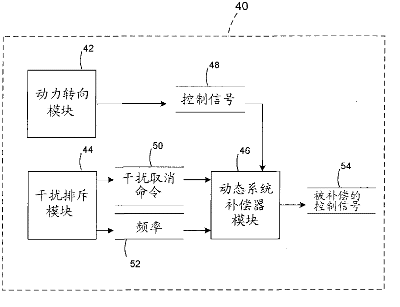
[0016] now refer to figure 1 , wherein the present invention will be described with reference to particular embodiments, but is not limited thereto, an exemplary embodiment of a vehicle 10 including a steering system 12 is shown. In various embodiments, the steering system 12 includes a handwheel 14 coupled to a steering shaft 16 . In an exemplary embodiment, the steering system 12 is an electronic power steering (EPS) system that further includes a steering assist unit 18 coupled to the steering shaft 16 of the steering system 12 and the tie rods 20 , 22 of the vehicle 10 . For example, the steering assist unit 18 includes a rack and pinion steering mechanism (not shown), which may be coupled to a steering ac...


PUM


Abstract

The invention relates to a dynamic system compensator for actively controlled power steering systems. A control method for an electric power steering system is provided. The method includes providing a power steering control signal; providing a disturbance cancel command; varying at least one filter based on a frequency of the disturbance cancel command; applying the at least one varied filter to the disturbance cancel command to generate a compensation signal; applying the compensation signal to the power steering control signal to generate a compensated control signal; and controlling the power steering system based on the compensated control signal.

Description

[0001] Cross References to Related Applications [0002] This patent application claims priority to US Provisional Patent Application Serial No. 61 / 360,808, filed July 1, 2010, which is hereby incorporated by reference in its entirety. technical field [0003] The present invention relates to a dynamic system compensator for an actively controlled power steering system, and more particularly to a method of compensating the dynamic response of a physical system. Background technique [0004] Actively controlled power steering systems are designed to assist the driver when steering the vehicle. Additional features are provided to produce acceptable steering feel response. A number of algorithms have been developed for such systems to achieve these objectives, working over an operating frequency range typically from 0 to 30 Hz. For some algorithms designed to work at higher frequencies, typically above 5 Hz, it has been observed that the performance of the algorithms does not...

Claims


Application Information

Patent Timeline
Patent Type & Authority Applications(China)
IPC IPC(8): B62D6/00B62D5/04B62D131/00B62D119/00B62D113/00
CPCB62D5/0472B62D5/0457B62D5/0463B62D5/0481B62D6/00
Inventor M·K·黑尔斯A·J·尚帕涅
Owner NEXTEER BEIJING TECH
Learn More