
Photoelectric wireless mouse

A wireless mouse and mouse technology, applied in the direction of light source, circuit layout, point light source, etc., can solve the problem of high cost, achieve the effect of cost reduction, convenient application, and anti-turbulence application

Inactive Publication Date: 2012-01-25
JINAN UNIVERSITY
View PDF6 Cites 4 Cited by
  • Summary
  • Abstract
  • Description
  • Claims
  • Application Information

AI Technical Summary

Problems solved by technology

However, the mouse includes two independent systems, namely the trackball system and the optical sensing system. There are two independent optical paths, and two optical engines are required, that is, two photodetectors and two sets of processing circuits are required. ,high cost

Method used


Image

  • Photoelectric wireless mouse
  • Photoelectric wireless mouse
  • Photoelectric wireless mouse

Examples


Embodiment Construction

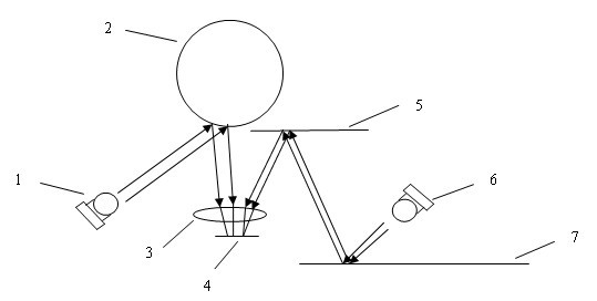
[0023] figure 1 It is a schematic diagram of the optical path of the mouse. In the optical path of the optical trackball, the first LED light source 1 is irradiated on the optical trackball 2, reflected by the optical trackball 2, and then reaches the photodetector 4 through the lens 3. When the optical trackball 2 is rotated, the feedback The image to the photodetector 4 changes to realize the determination of the position of the mouse cursor; the second LED light source 6 illuminates the desktop, and through the reflection of the desktop, the reflected light reaches the plane mirror 5, and then through the reflection of the plane mirror, the light reaches the photodetector 4 through the lens 3, When the mouse body is moved, the second LED light source 6 irradiates the desktop, so that the image fed back to the photodetector 4 changes to realize the determination of the position of the mouse cursor.

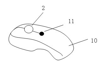
[0024] figure 2 It is a diagram above the mouse body. When holding the mo...


PUM


Abstract

The invention relates to a photoelectric wireless mouse. A left mouse button, a right mouse button and an optical trackball are arranged on a mouse body, and the optical trackball is arranged between the left mouse button and the right mouse button and comprises a first LED (light-emitting diode) light source and a second LED light source. The photoelectric wireless mouse is characterized by comprising a manual transfer switch, and a lens and a photodetector which are commonly used by two light paths, and the manual transfer switch is used for controlling the first LED light source and the second LED light source to be turned on or off; light emitted by the first LED light source is reflected by the optical trackball and then enters the photodetector through the lens, and light emitted by the second LED light source is reflected by a desktop, and then is reflected by a plane mirror inside the photoelectric mouse and then enters the photodetector through the lens; and the photoelectric mouse with an idler wheel is formed by a time division multiplexing mode that the two LED light sources are alternately turned on or off. The photoelectric wireless mouse has a compact structure and greatly reduced cost, and is very suitable for conference speeches or reports.

Description

technical field [0001] The invention relates to a photoelectric wireless mouse. Background technique [0002] The optical engine of the mouse is composed of a CMOS image sensor and an optical positioning DSP (digital signal processor). The optical engine of the photoelectric mouse with LED as the light source determines the position of the cursor by receiving the feedback image. The difference of feature points is used to judge the position information of the cursor. The track ball mouse is another type of optical mouse. When it is working, the ball seat is fixed, and the track ball can be moved directly by hand, and it can also be operated in the air. Its advantage is that it saves space and reduces the fatigue of the user's wrist. . [0003] The wireless technology of the wireless mouse has gone through four stages, infrared wireless, 27MHz wireless radio frequency, Bluetooth, 2.4GHz digital high-speed radio frequency. The 2.4GHz wireless technology is completely open, ...

Claims


Application Information

Patent Timeline
IPC IPC(8): G06F3/033F21V23/04F21Y101/02G06F3/0354
Inventor 张军陈哲周冬花袁建平王红印余健辉
Owner JINAN UNIVERSITY
Learn More