
Method and apparatus for simulation test of gas temperature control valve

A technology for simulating testing and testing devices, applied in the field of testing the opening and closing performance of gas valves, can solve problems such as low work efficiency, complex testing devices, long testing time, etc. high effect

Active Publication Date: 2012-01-25
ZHEJIANG CHUNHUI INTELLIGENT CONTROL
View PDF6 Cites 2 Cited by
  • Summary
  • Abstract
  • Description
  • Claims
  • Application Information

AI Technical Summary

Problems solved by technology

[0003] At present, the working characteristics test of the simulation test of the gas temperature control valve is only limited to the laboratory. The temperature sensing element is immersed in a bath at a rate of 0.5K / min. Expansion, so that the moving rod of the gas temperature control valve moves until the valve is closed, and then the temperature is lowered at the same speed until the temperature control valve is opened. During the test, the flow corresponding to each temperature point is recorded, and the temperature-flow curve is drawn. This test method It has the advantages of good simulation, but its test requires temperature sensing elements, baths and bath temperature control devices, so there is a lack of complex test devices, and the setting of representative temperature points is limited. Generally, only three can be measured by the above test method. The flow rate at representative temperature points, such as the flow rate at full open high flow rate, low flow rate, and fully closed point, is used to judge whether the working characteristics meet the requirements, which cannot reflect the working characteristics throughout the process, and there are quality risks
At the same time, the test time is long and the work efficiency is low, so it is not suitable for testing one by one during mass production

Method used


Image

  • Method and apparatus for simulation test of gas temperature control valve
  • Method and apparatus for simulation test of gas temperature control valve
  • Method and apparatus for simulation test of gas temperature control valve

Examples


Embodiment Construction

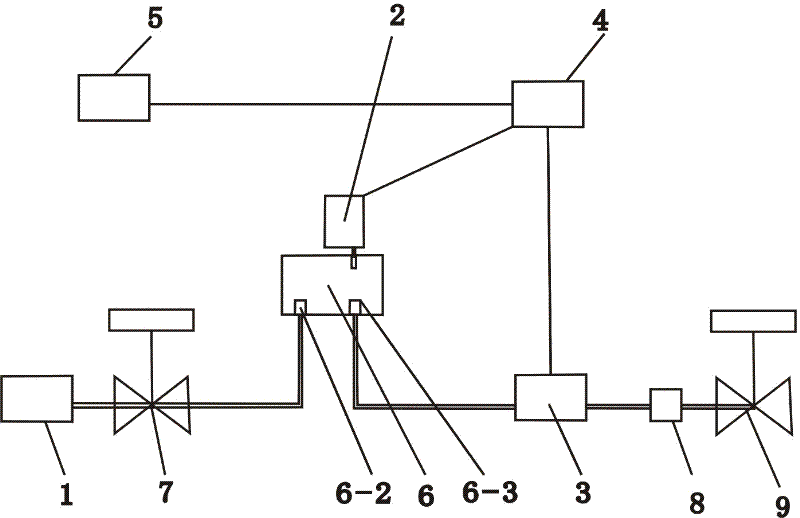
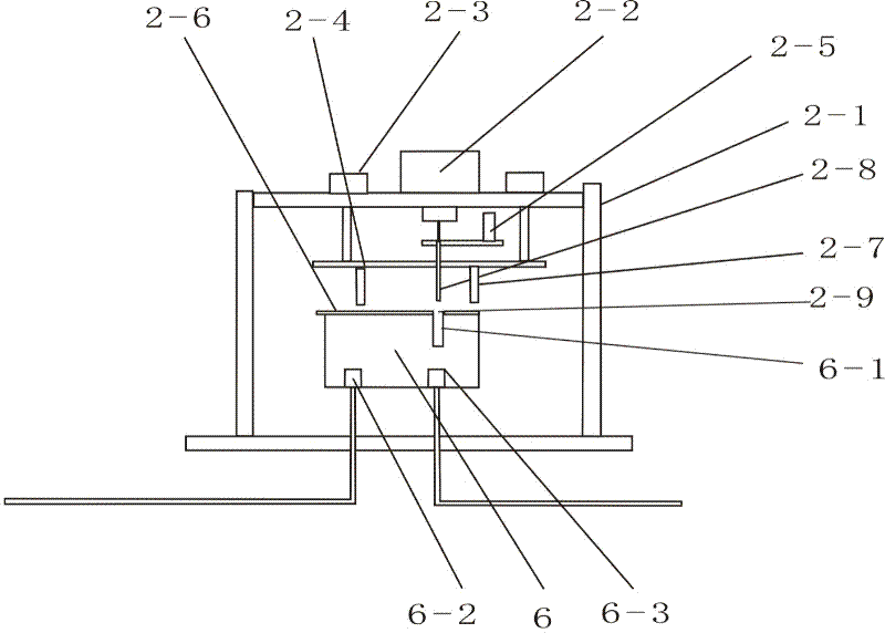
[0016] The simulation test method of the gas temperature control valve of the present invention uses air as the test medium, replaces the volume expansion and contraction of the temperature sensing element with the linear drive of the linear stepping motor to generate a linear displacement, and moves the moving rod of the gas temperature control valve to control the temperature. Control the flow rate of the valve and the opening and closing of the valve port to achieve the purpose of changing the gas flow and opening and closing; and the number of motor pulses under the same flow rate corresponds to the equivalent actual temperature, and the characteristic curve of temperature and flow rate is displayed on the display; The standard range for good curve judgment can automatically judge whether the function curve of the test valve meets the requirements.

[0017] The speed of the linear stepper motor is adjustable, and the high speed can be set during the idle stroke, which can m...


PUM


Abstract

The invention discloses a test device for a gas temperature control valve. According to the method, air is utilized as a testing medium; linear drive of a linear stepping motor replaces volume expansion and volume contraction of a temperature-sensing element to generate a linear displacement, so that a flow of a temperature control valve is controlled; motor pulse numbers at same flows are corresponded to equivalent actual temperatures; and a standard range of curve determination is arranged and it is determined whether a functional curve of a testing valve meets a requirement. The simulation test apparatus comprises a gas source assembly, a movable lever driving assembly, a flow induction assembly, a control assembly and a display assembly. The gas source assembly and the flow induction assembly are respectively connected with a gas inlet and a gas outlet of a detected gas temperature control valve; and the control assembly is respectively connected with a movable lever driving assembly signal, a flow induction assembly signal, and a display assembly signal. The above-mentioned scheme of the invention has characteristics of rapidity and accuracy and the like; a working characteristic of a gas temperature control valve in a whole course can be reflected and a quality hidden trouble of the gas temperature control valve can also be eliminated. Moreover, the apparatus is suitable for one-by-one test during batch production.

Description

technical field [0001] The patent of the present invention relates to a testing method and device, in particular to a testing method and device for testing the opening and closing performance of a gas valve, belonging to the technical field of assembly and testing of gas temperature control valves. Background technique [0002] The gas temperature control valve controls the flow rate of the valve through the change of temperature. The existing mechanical gas temperature control valve includes a valve body and a displacement rod. The valve body is provided with an air inlet and an air outlet. The change produces a change in its volume, which moves the displacement rod and realizes the control of the valve flow. For a specific introduction to the mechanical gas temperature control valve, please refer to the patent document "A Gas Temperature Control Valve" published by the State Intellectual Property Office on December 20, 2006, publication number: CN2849375. [0003] At pres...

Claims


Application Information

Patent Timeline
Patent Type & Authority Applications(China)
IPC IPC(8): G01M13/00
Inventor 梁丽君景江兴於军标杭一勇徐杰徐志达
Owner ZHEJIANG CHUNHUI INTELLIGENT CONTROL
Learn More