
Biomass gasification device and process

A biomass and equipment technology, applied in the field of biomass gasification equipment and gasification process, can solve the problems of inability to continuously and stably generate electricity by gas generator sets, inconvenient storage and transportation for large-scale promotion and application, damage and corrosion of terminal application equipment, etc. Controllable leveling operation, improving gasification efficiency and gas calorific value, and prolonging service life

Inactive Publication Date: 2012-01-25
张建超
View PDF8 Cites 9 Cited by
  • Summary
  • Abstract
  • Description
  • Claims
  • Application Information

AI Technical Summary

Problems solved by technology

The chemical energy stored in these biomasses is more than three times the world's total energy consumption, but our current utilization rate is less than 3% of the total
[0004] Existing biomass gasification equipment uses anaerobic combustion to generate combustible gas, but due to its simple structure and unreasonable design, there are many defects, such as: long smoke exhaust time, polluting the environment, unstable gas production, and high tar content in gas production. Blockage of gas pipelines, or damage and corrosion of terminal application equipment
Therefore, it cannot be used continuously for a long time, it is not convenient for storage and transportation or large-scale promotion and application, and it cannot be applied to continuous and stable power generation of existing gas-fired generator sets

Method used


Image

  • Biomass gasification device and process
  • Biomass gasification device and process
  • Biomass gasification device and process

Examples


Embodiment Construction

[0060] The present invention will be further described in detail below in conjunction with the accompanying drawings.

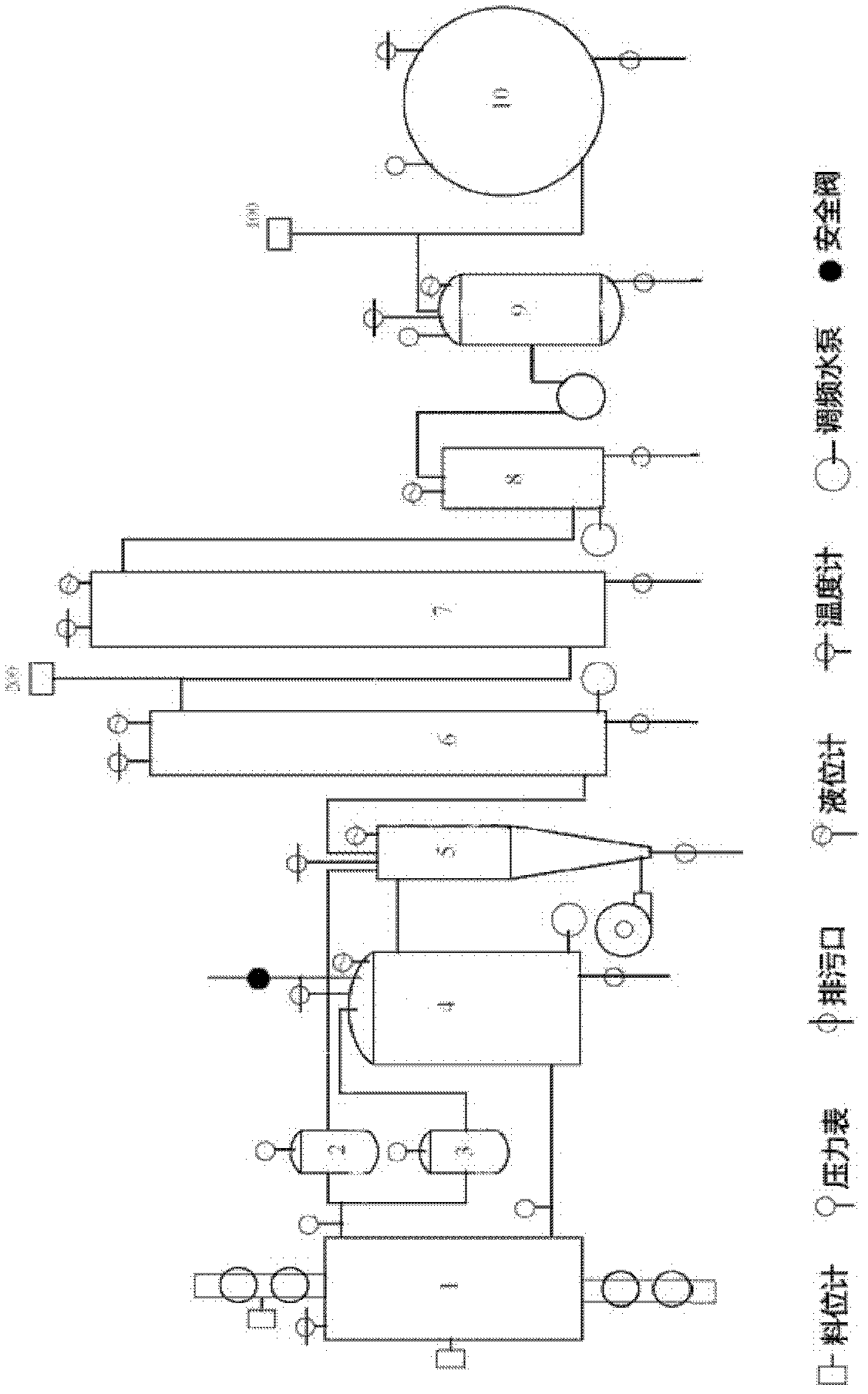
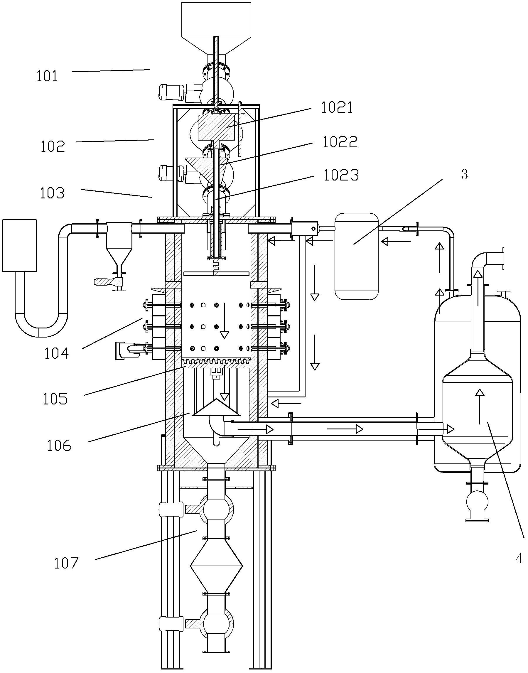
[0061] A biomass gasification equipment, such as figure 1 As shown, it includes gasification reaction chamber 1, air buffer tank 2, steam buffer tank 3, steam heat exchanger 4, internal and external double cyclone heat exchange dust collector 5, cooling tower 6, electric tar catcher connected in sequence by gas pipeline 7. Hydrogen sulfide removal sprayer 8, gas-water separator 9 and gas storage tank 10;

[0062] The steam heat exchanger 4, the steam buffer tank 3, and the gasification reaction chamber 1 are connected in sequence through a steam pipeline; the blower, the inner and outer double cyclone heat exchange dust collector 5, the air buffer tank 2, and the gasification reaction chamber 1 are connected in sequence through an air pipeline; Gas) The gas storage tank 10 is connected to the user end gas application equipment or the gas pipeline network thr...


PUM

PropertyMeasurementUnit
widthaaaaaaaaaa

Abstract

The invention relates to a biomass gasification device and process. The device comprises a gasification reaction chamber, a steam heat exchanger, a steam buffer tank, an air buffer tank, an inner and outer double-cyclone heat exchanging dust collector, a cooling tower, an electro tar precipitator, a hydrogen sulfide removal sprayer, a water ring compressor, a gas-water separator, a gas storage tank and a control system of the device, which are connected through a gas pipeline; the gasification reaction chamber comprises an automatic feeding device, a two-stage gasification zone, a vibrating grate, an automatic ignition device, an automatic slagging device and an automatic leveling device. The gasification process comprises the following steps of: gas generation; gasification medium preheating; gas purifying and filtering; and gas compression and storage. The biomass gasification device and process are scientific and environment friendly, have the remarkable characteristics of simple structural design, high degree of automation as well as stable, controllable and continuous gasification reaction, have high gasification efficiency and entire caloricity, are suitable for popularization and application on a large scale, and are particularly applicable to continuous and stable generation of the traditional gas generating set.

Description

technical field [0001] The invention relates to dry distillation of carbonaceous materials to produce fuel gas, in particular to biomass gasification equipment and a gasification process. Background technique [0002] Energy and environmental protection are two major problems that need to be solved in the world today. Most of the energy supply still relies on fossil fuels, but the various pollutants emitted during combustion make the environmental problems worse. At the same time, it is well known that the fossil fuels we use come from biomass, which is actually a 100% renewable and clean energy. [0003] In a broad sense, biomass includes all plants, microorganisms, animals, and the wastes they produce. Biomass resources are very rich, such as municipal solid waste (MSW), forest trees, agricultural waste and other carbon-rich organic materials are excellent biomass resources. Every year, 140-180 billion tons of biomass are generated on the earth due to photosynthesis base...

Claims


Application Information

Patent Timeline
Patent Type & Authority Applications(China)
IPC IPC(8): C10J3/60C10J3/66C10J3/20C10J3/30C10J3/34C10J3/84C10J3/80C10J3/72
Inventor 张建超张瑜姜晨旭唐旻张建国
Owner 张建超
Learn More