Method for treating and printing and dyeing wastewater by using hydrolysis tank

A technology of printing and dyeing wastewater and hydrolysis pool, which is applied in textile industry wastewater treatment, multi-stage water/sewage treatment, biological water/sewage treatment, etc. It can solve the problems of no successful cases, reduced effective pool capacity, and reduced treatment efficiency. Achieve the effects of easy film formation, promotion of metabolism and renewal, and improvement of treatment efficacy

Active Publication Date: 2012-01-25
ZHEJIANG SHUANGLIANG SUNDA ENVIRONMENTAL PROTECTION CO LTD
View PDF2 Cites 8 Cited by
  • Summary
  • Abstract
  • Description
  • Claims
  • Application Information

AI Technical Summary

Problems solved by technology

At present, there are many design schemes for the design of hydrolytic acidification tanks. The bottom perforated water distribution type is widely used, but for the traditional design of hanging film type hydrolysis acidification tanks, it has been applied to a certain extent in the field of printing and dyeing wastewater, but there are almost no successful cases. Basically, a large amount of facultative mud in the hydrolytic acidification tank is deposited on the bottom, resulting in a decrease in the effective tank capacity and a decrease in treatment efficiency

Method used


Image

  • Method for treating and printing and dyeing wastewater by using hydrolysis tank
  • Method for treating and printing and dyeing wastewater by using hydrolysis tank
  • Method for treating and printing and dyeing wastewater by using hydrolysis tank

Examples


Embodiment 1

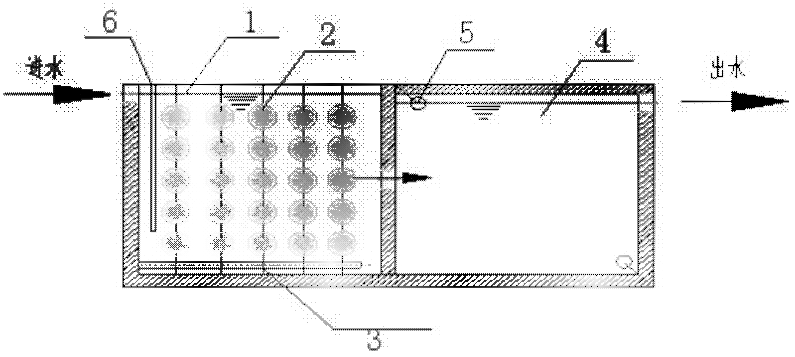
[0025] The printing and dyeing wastewater is biodegradable wastewater containing PVA slurry; the hydrolysis pool is divided into two parts, the first half pool 1 and the second half pool 4, the first half pool of the hydrolysis pool has a water inlet, and the second half pool of the hydrolysis pool has a water inlet. Water outlet, the second half pool 4 is connected in series with the oxidation ditch 10 and the secondary sedimentation tank 11; the first half pool 1 is an open pool with an upper opening, and the first half pool 1 is added with filler 2, and the first half pool 1 A perforated intermittent aerator 3 is arranged at the bottom, and a baffle plate 6 is arranged at the water inlet of the first half pool 1, and the baffle plate is suspended above the first half pool of the hydrolysis tank, and the height of the baffle plate is less than the depth of the hydrolysis tank; The half pool 4 is a closed pool closed above, and there are submersible mixers 5 at both ends of a ...


PUM


Abstract

The invention discloses a method for treating and printing and dyeing wastewater by using a hydrolysis tank. The hydrolysis tank comprises a front half tank and a rear half tank, wherein the front half tank of the hydrolysis tank is provided with a water inlet; the rear half tank of the hydrolysis tank is provided with a water outlet; the rear half tank is connected with an oxidation ditch and a secondary sedimentation tank in series; the front half tank is an opened tank of which the upper part is opened; the rear half tank is a closed tank of which the upper part is closed; the printing anddyeing wastewater is treated and then is mixed with sludge in the secondary sedimentation tank at the water inlet; the mixture enters the inside of the front half tank of the hydrolysis tank from thelower part of a baffle plate; when DO value of the printing and dyeing wastewater reaches 0.2-0.3mg / L, the wastewater enters the interior of the rear half tank of the hydrolysis tank; and when the DOvalue of the printing and dyeing wastewater reaches 0.3-0.5mg / L, the wastewater is discharged after reaching the standard. According to the method disclosed by the invention, the biochemical quality of the hydrolysis tank is greatly improved; the ammonifying effect of organisms which are difficult to degrade, such as organic nitrogen, is remarkably improved; and the removal rates of subsequent COD (Chemical Oxygen Demand) and NH3-N are greatly improved.

Description

(1) Technical field [0001] The invention relates to a wastewater treatment method, in particular to a method for treating printing and dyeing wastewater by using a hydrolysis tank. (2) Background technology [0002] The printing and dyeing industry is closely related to the lives of the people in our country and occupies a very important position in the national economy. However, the annual discharge of printing and dyeing wastewater pollution is also considerable. According to relevant domestic and foreign data estimates, the water consumption for processing a piece of cotton fabric is about 1-1.2m 3 . Printing and dyeing wastewater is characterized by large water volume, high content of organic pollutants, low B / C ratio, deep chroma, high alkalinity, and large changes in water quality. It is a difficult-to-treat industrial wastewater. As the sustainable development strategy has become the consensus of people all over the world, my country has gradually increased the inte...

Claims


Application Information

Patent Timeline
IPC IPC(8): C02F9/14C02F3/10C02F3/12C02F103/30
CPCY02W10/10
Inventor 郑展望裴刚
Owner ZHEJIANG SHUANGLIANG SUNDA ENVIRONMENTAL PROTECTION CO LTD
Why Eureka
Try Eureka