
Flash butt welding machine

A technology for butt welding machines and chains, applied in welding equipment, resistance welding equipment, welding/welding/cutting items, etc., it can solve the problems of slow response speed, cumbersome feeding mechanism, and many components, etc., and achieves an improved response speed. Effect

Active Publication Date: 2012-01-25
ZHANGJIAKOU NORTH WELDING MACHINE CO LTD
View PDF7 Cites 9 Cited by
  • Summary
  • Abstract
  • Description
  • Claims
  • Application Information

AI Technical Summary

Problems solved by technology

There are many deficiencies in the existing chain flash butt welding machines, such as heavy feeding mechanism, large friction coefficient, and slow response speed, which seriously affect the response speed of the system during the flash feeding process, resulting in chain welding strength and welding yield. It is difficult to meet the needs of product production; moreover, the welding control system uses an analog circuit control method. On the one hand, the electronic circuit structure is complex and there are many components. Once a fault occurs, it is very difficult to repair. To adjust the welding parameters, it is necessary to rely on manual experience to adjust parameters such as extension length, flash current, flash flow, flash speed, upsetting flow, upsetting speed, upsetting pressure, upsetting current, and clamping force in the process. Adjusted, so product quality is difficult to control

Method used

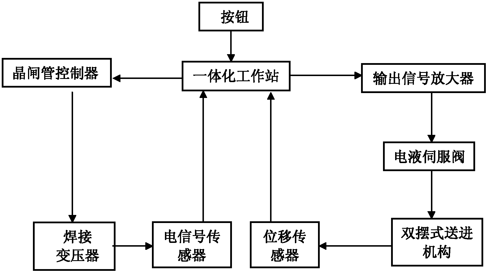
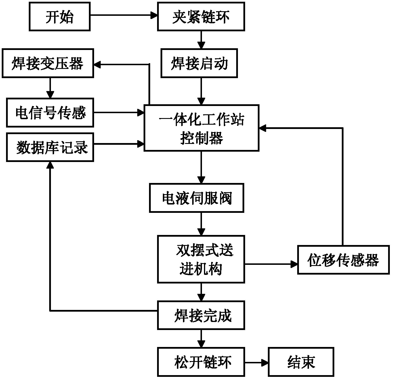

Image

  • Flash butt welding machine
  • Flash butt welding machine
  • Flash butt welding machine

Examples


Embodiment Construction

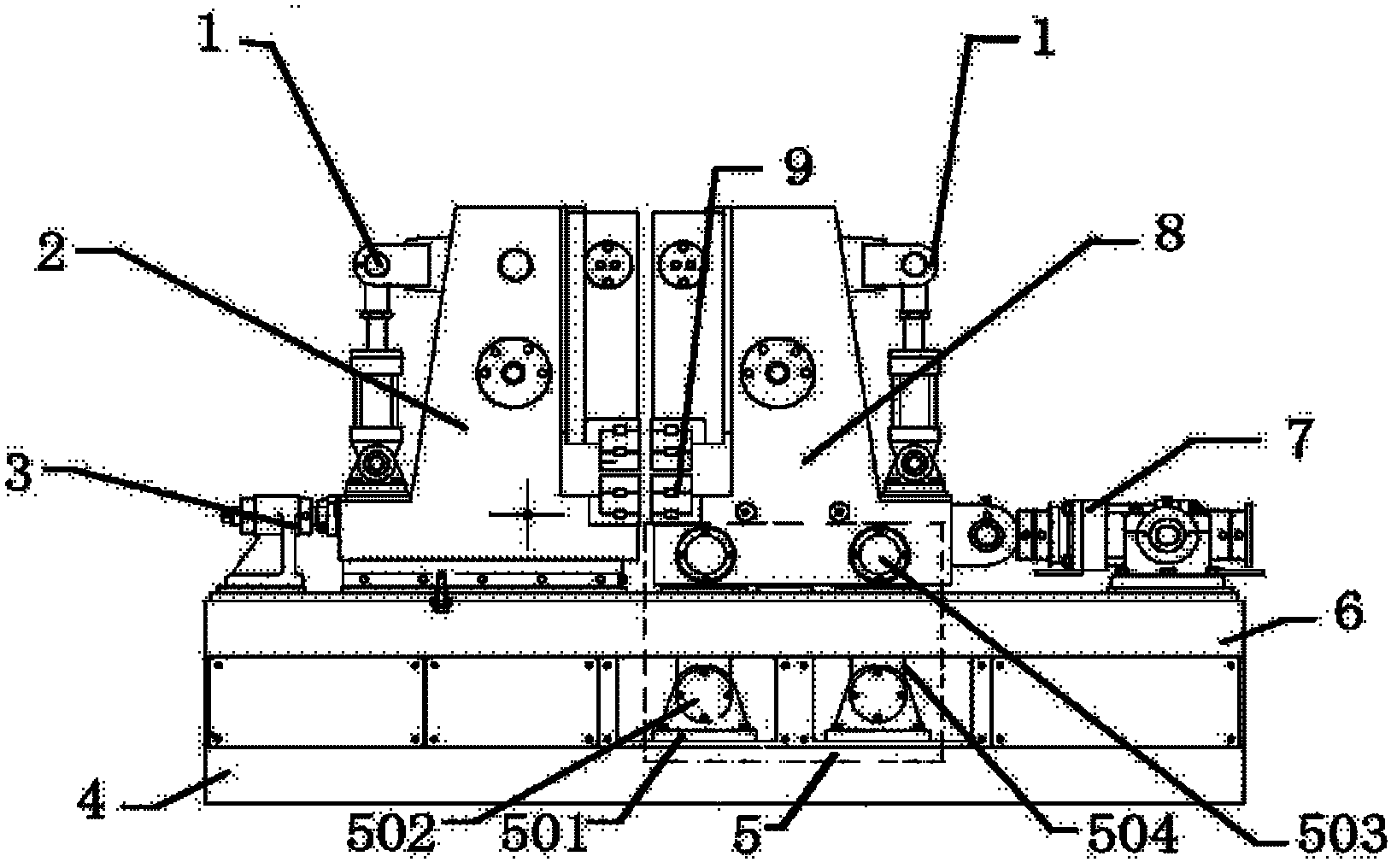
[0012] Such as figure 1 Shown, the present invention support 4, frame 6, send drive device 7, welding control system, fixed workbench 2, movable workbench 8. Left and right two sliding guide rails are installed on the table top of the frame 6 of the main engine, and the fixed workbench 2 and the movable workbench 8 are respectively housed on the left and right two guide rails. Clamping mechanism 1 is arranged, and this clamping mechanism 1 comprises oil cylinder piston rod, clamping slide block, and oil cylinder piston rod moves up and down through lever and drives clamping slide block to move up and down, and the workpiece to be welded is clamped. The upper and lower electrodes and the upper and lower conductors 9 are installed on the frame of the fixed workbench 2 and the movable workbench 8 according to the conventional design. The bottom of the movable table 8 is provided with a double pendulum feeding mechanism 5, which includes an upper swing shaft 503 and a lower swing...


PUM


Abstract

The invention discloses a flash butt welding machine, which can be used for effectively improving the welding quality and efficiency of a chain. The flash butt welding machine comprises a base, a frame, a feed-in driving device, a welding control system, a fixed workbench and a movable workbench, wherein a guide rail is arranged on the stand, and clamping mechanisms are arranged on the fixed workbench and the movable workbench. The flash butt welding machine is characterized in that: a double-pendulum type feeding-in mechanism is arranged at the bottom of the movable workbench and comprises an upper pendulum shaft and a lower pendulum shaft, wherein the upper pendulum shaft is fixed at the bottom of the movable workbench, the lower pendulum shaft is fixed on the base through a pendulum shaft seat, and the upper pendulum shaft and the lower pendulum shaft are connected through a pendulum arm. According to the flash butt welding machine, the resistance of the movable workbench in the feeding process is greatly reduced, so that the movable workbench is fed more portably, flexibly and rapidly, therefore the requirement of rapid response of the welding process is met, and the welding quality and efficiency are improved.

Description

technical field [0001] The present invention relates to welding equipment, in particular to a chain flash butt welding machine. Background technique [0002] Chain flash butt welding machine is widely used in welding of high-strength mining chains, anchor chains, cement chains, lifting chains, etc. and various special-shaped workpieces. The chain flash butt welding machine usually includes a machine base, a feeding mechanism, an upsetting mechanism, a welding control system, a fixed workbench, and a movable workbench. Guide rails are provided on the machine base, and clamping mechanisms are provided on the fixed workbench and the movable workbench. , the movable table can move relatively on the guide rail of the machine base through pulleys. There are many deficiencies in the existing chain flash butt welding machines, such as heavy feeding mechanism, large friction coefficient, and slow response speed, which seriously affect the response speed of the system during the flas...

Claims


Application Information

Patent Timeline
IPC IPC(8): B23K11/04B23K11/36B23K101/30
Inventor 张学斌胡智明
Owner ZHANGJIAKOU NORTH WELDING MACHINE CO LTD
Learn More